Service Manuals, User Guides, Schematic Diagrams or docs for : Philips Monitor CD 2001 Monitor CD 2001 E-MANUALS Philips crt 109b2 pdf p08
<< Back | HomeMost service manuals and schematics are PDF files, so You will need Adobre Acrobat Reader to view : Acrobat Download Some of the files are DjVu format. Readers and resources available here : DjVu Resources
For the compressed files, most common are zip and rar. Please, extract files with Your favorite compression software ( WinZip, WinRAR ... ) before viewing. If a document has multiple parts, You should download all, before extracting.
Good luck. Repair on Your own risk. Make sure You know what You are doing.
Image preview - the first page of the document
>> Download p08 documenatation <<
Text preview - extract from the document
 8     109B2 GS3 CM25                                 Mechanical Instructions
     Go to cover page

0. Location of the panel
0.1 Main panel (1155)
0.2 Video panel (1157)


1. General
To be able to perform measurements and repairs on the "circuit
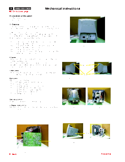
boards", the monitor should be placed in Service Position (fig. 1) first:

How to remove the back cover of monitor :
There are 2 screws in the lid [1 screw are at the right side of the
monitor, the other 1 screw are at the left side of the monitor],to fix the
front cabinet and back cover of the monitor.

Step 1: To open the lid at the right-upper side and 1screw in right-
        downer side of the monitor.(FIG.3)
Step 2: To open the lid at the left-upper side and 1screw in left-                             Fig. 2
        downer side of the monitor.(FIG.4)
Step 3: To remove the backcover, you can see FIG.5
Step 4: To remove the16 screws on the metal shield, and remove the
        metal shield, you can see FIG.6.

Chassis :
- After remove the back cover & metal shield, you can see the inside
    of the monitor as Fig. 6.
- To remove 5 screws for service position as Fig. 6 to Fig. 8.
- Including remove bottom plate screw, then slide out chassis board                             lids
    and disconnect metal shield.

Video panel :
- After remove the metal frame (Fig. 5), to remove the metal shield on
   rear side of Video panel for measurement.                                                    screws
                                                                             Fig. 3                          Fig. 4
Main panel :
After remove the metal frame.
- To cut out cable tie and disconnect "video panel"
- To disconnect EHT cable
- To disconnect ground wire(1703) of video board.
- To disconnect M1802(6pin) to control panel.
- To disconnect M1401(4pin) yoke connector.
- To disconnect M1603(2pin) degaussing coil
- To slide out Main panel as Fig. 1.


Service position :
To get service position as Fig. 1 through Fig. 2 to Fig. 8.

2. Repair instructions
After the service position was obtained, all the panel's copper track                 Fig. 5               Fig. 6
side could be accessed.


                                                                                                   screw
  1157


                                                                1155
                                                                                      Fig. 7               Fig. 8


                    Fig. 1 Service Position
     Back                                                                                                       Forward
◦ Jabse Service Manual Search 2026 ◦ Jabse Pravopis ◦ onTap.bg ◦ Other service manual resources online : Fixya ◦ eServiceinfo