Service Manuals, User Guides, Schematic Diagrams or docs for : Philips Monitor Monitor CD 2001[1].part02 Monitor CD 2001 E-MANUALS Philips crt 104s PDF p16-19

<< Back | Home

Most service manuals and schematics are PDF files, so You will need Adobre Acrobat Reader to view : Acrobat Download Some of the files are DjVu format. Readers and resources available here : DjVu Resources
For the compressed files, most common are zip and rar. Please, extract files with Your favorite compression software ( WinZip, WinRAR ... ) before viewing. If a document has multiple parts, You should download all, before extracting.
Good luck. Repair on Your own risk. Make sure You know what You are doing.


Image preview - the first page of the document
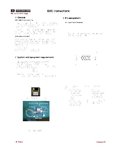
p16-19


>> Download p16-19 documenatation <<

Text preview - extract from the document
16     104S CM23 GSIII                                          DDC Instructions
     Go to cover page

      1. General                                                                 3. Pin assignment
      DDC Data Re-programming
                                                                                    A. 15-pin D-Sub Connector
      In case the main EEPROM with Software DDC which store all factory
      settings were replaced because a defect,repaired monitor' the serial
      numbers have to be re-programmed.

      It is advised to re-soldered the main EEPROM with Software DDC from
      the old board onto the new board if circuit board have been replaced, in
      this case the DDC data does not need to be re-programmed.                        The 15-pin D-sub connector (male) of the signal cable
                                                                                       on the 3rd row for DDC feature :
      Additional information

      Additional information about DDC (Display Data Channel) may be
      obtained from Video Electronics Standards Association (VESA).
      Extended Display Identification Data(EDID) information may be also
      obtained from VESA.

      DDC EDID structure
      For the monitor   : Standard Version 3.0
                          Structure Version 1.2


                                                                                                       1                             5
      2. System and equipment requirements                                                             6                            10
                                                                                                      11                            15
      1. An i486 (or above) personal computer or compatible.
      2. Microsoft operation system Windows 95/98.
      3. EDID301.EXE program (3138 106 10103) shown as Fig. 1
      4. Software DDC Alignment kits (4822 310 11184) shown as Fig. 2.
      The kit contents: a. Alignment box x1
                        b. Printer cable x1
                        c. D-Sub cable x1

          Note: The EDID301.EXE (Release Version 1.54) is a
                 windows-based program, which cannot be run in MS-DOS.


                                                                                 Pin No.   Assignment                Pin No.    Assignment

                                                                                   1       Red video input            9        No pin
                                                                                   2       Green video input          10       Logic ground
                                   EDID301.EXE
                                                                                   3       Blue video input           11       Identification output -
                                     Ver:1.54
                                                                                   4       Identification output -             Connected to pin 10
                                                                                           Connected to pin 10        12       Serial data line(SDA)
                      Figure 1 Diskette with EDID301.EXE                           5       Ground                     13       H.Sync
                                                                                   6       Red video ground           14       V.Sync(VCLK for DDC)
                            DC 8V~12V            Power indicator                   7       Green video ground         15       Data clock line(SCL)
                                                                                   8       Blue video ground
                             To Monitor            To Printer


                                       Video Card


                            Fig. 2 Alignment Kits


           Back                                                                                                                          Forward
                                                                                      DDC Instructions                                                                         104S CM 23 GSIII             17
                                                                                                                                                                                  Go to cover page

4. Configuration and procedure                                                                   Re-programming Software DDC

Following descirptions are the connection and procedure for Software                             Step 1: After initialize alignment box, connecting all cables and box as
DDC, the main EEPROM can be re-programmed along with Software                                            Fig. 3
DDC by enabling "factory memory data write" function on the DDC                                  Step 2: Follow the steps on DDC re-programming instructions to staring
program (EDID301.EXE).                                                                                   re-programming.

To access factory mode:                                                                                                                                                          Rear view of the monitor
Turn off monitor (don't turn off PC)
- Press "       " and "        " simultaneously on the front control panel                                     PC
  ,then press "     ",wait till the OSD menu with characters
 " factory mode (below OSD menu)" come on the screen of monitor.


                                                                                                                         To printer port (LTP1)
Initialize alignment box
                                                                                                                                                       DC Power


                                                                                                         To video card
                                                                                                                                                        8~12 V
In order to avoid that monitor entering power saving mode due to                                                                                             ~
sync will cut off by alignment box, it is necessary to initialize
alignment box before running programming software                                                                                                                               Video cable
(EDID301.EXE). Following steps show you the procedures and
                                                                                                                                                                 To
connection.                                                                                                                                                      Monitor
                                                                                                                                                       Printer
                                                                                                                                                       Port
Step 1: Supply 8~12V DC power source to the Alignment box by                                                                                                      To PC
        plugging a DC power cord or using batteries.
Step 2: Connecting printer cable and video cable of monitor as Fig. A
Step 3: Run the EDID301.EXE program until the main menu appears.                                                                                            Fig. 3
        This is for initialize alignment box.
                                                                                                  5. DDC re-programming instructions
                                                                                                       Start on DDC program
                                                                     Rear view of the monitor     Start Microsoft Windows.
                                                                                                  1. Insert the disk containing EDID301.EXE program into floppy disk
                                                                                                     drive.
                                                                                                  2. Click          , choose Run at start menu of Windows 95/98.


                                                                                   Video cable
                     PC
                              To printer port (LTP1)


                                                       DC Power
              To video card


                                                        8~12 V
                                                             ~
                                                                                                 4. At the submenu, type the letter of your computer's floppy disk drive
                                                                                                    followed by :EDID301 (for example, A:\EDID301, as shown in Fig. 5).
                                                                 To
                                                                 Monitor
                                                       Printer
                                                       Port

                                                                  To PC


                                                            Fig. A
                                                                                                                                                  A:\edid301


◦ Jabse Service Manual Search 2026 ◦ Jabse PravopisonTap.bg ◦ Other service manual resources online : FixyaeServiceinfo