Service Manuals, User Guides, Schematic Diagrams or docs for : Philips Monitor Monitor CD 2001[1].part02 Monitor CD 2001 E-MANUALS Philips crt 105s2 pdf p41-48R

<< Back | Home

Most service manuals and schematics are PDF files, so You will need Adobre Acrobat Reader to view : Acrobat Download Some of the files are DjVu format. Readers and resources available here : DjVu Resources
For the compressed files, most common are zip and rar. Please, extract files with Your favorite compression software ( WinZip, WinRAR ... ) before viewing. If a document has multiple parts, You should download all, before extracting.
Good luck. Repair on Your own risk. Make sure You know what You are doing.


Image preview - the first page of the document
p41-48R


>> Download p41-48R documenatation <<

Text preview - extract from the document
                                       Repair flow chart                                              105S2 CM23 GSIII      41
                                                                                                  9 Go to cover page


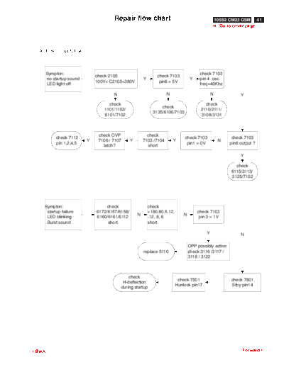
  A. Power Supply Failure


        Sympton:                                                                           check 7103
                               check 2105                        check 7103
        no startup sound                                 Y                            Y    pin 4 osc.
                               100V< C2105<380V                   pin8 = 5V
        LED light off                                                                      freq=40Khz

                                       N                              N                           N              Y

                                    check                                                    check
                                                                   check
                                  1101/1102/                                               2110/2111/
                                                               3135/6106/7103
                                  6101/7102                                                3108/3131


                                check OVP                  check
            check 7112                                                           check 7103                  check 7103
                           Y    7106 / 7107      Y       7103 /7104       Y                            N
            pin 1,2,4,5                                                           pin1 = 0V                 pin6 output ?
                                  latch?                   short

                                                                                                                 Y

                                                                                                               check
                                                                                                             6115/3113/
                                                                                                             3125/7102


    Sympton:                        check                    check
     startup failure           6172/6157/6158/               +180,80,5,12,                check 7103
                                                     N                           N
     LED blinking              6160/6161/6112                -12, 8, 6                     pin 3 > 1V
     Burst sound                    short                    short

                                                                                              Y                  N

                                                                                     OPP possibly active
                                                         replace 5110                check 3116 /3117 /
                                                                                     3118 / 3122


                                               check
                                                                              check 7501                     check 7801
                                            H-deflection
                                                                             Hunlock pin17                   Stby pin14
                                           during startup


3Back                                                                                                             Forward4
42    105S2 CM23 GSIII                             Repair Flow Chart
9 Go to cover page

                                  check R,G, B input / output
  B.Video                         1. video input= 0.7V
    Repair Flow                   2. 7301video output =2.5V
                                  3. 7701 video output= 35V swing


  1.Sympton :
    ( input a white pattern signal )           check                check                   check
                                                                                  Ok
    no picture                               heater = 6V          EHT=25KV                VG1< -100V
    green LED on
                                                                      N                         Y

                                                                check Xay-prot.             check             N
                                                                  7501 pin2               7501 pin17


                                                                                  check R,G,B output
                                                       check                         30<2725<80
                        check CRT           Ok                        Y
                                                     VG2 > 400V                      30<2733<80
                                                                                     30<2753<80

                                                                                          N

                                                                                  check DC restoration
                                             check blanking
                                                                                    7722,7732,7752
                                               7501 pin16
                                                                                    7721,7731,7751

                                                    Ok

  2.Sympton :
                                                 check VG1                turn high           check +80V
    no video ( or dim )                                         N
                                                 VG1 <-100V                  VG2                supply
    only raster with green LED

                                                                                                              N

                      check 7301                  check 7301           check 7701             check 7701
                        pin24          Ok          pin 6,8,10           pin 8,9,11             pin 1,3,5
                     2V< ABL < 5V                 input swing          input swing            output swing

                                                     No                     Ok

                      check 7301                    check
                      pin11 HFLB                                      replace 7701
                                                   IF cable


                       check 7301
                                       Ok        replace 7301
                       pin5 CLBL


                           No


                       check 7501
                         pin16
3Back                                                                                                    Forward4
                                          Repair flow chart                                          105S2 CM23 GSIII           43
                                                                                                    9 Go to cover page


    C. Horizontal deflection
      output repair flow :


    1. Sympton :
                                check Hsync              check Hsync              check Hsync
      without
                                 7606 base                7605 gate                7501 pin8
      H-deflection.


                                             check                      check Hsync
               replace 5611                                                                              check Hsync
                                  Ok       7623 drain         Ok         7621/ 7622            Ok
                                                                                                          7501 pin6
                                             180V                      emitter/collector

                                                N                             N                                 N

                                       check short circuit               check                              refer 7501
                                          5611 pin4                  6631,7621,7622                          check list


    2. Sympton :                                              check                  check 7503
                                check 2629                                                                        refer 7503
       East /West                                N       7610/7611/7612       N         pin11           N
                               parabola exist                                                                      check list
       corr. fail                                         parabola exist            parabola exist


    3. Sympton :                  Enter factory mode
                                                                         check                            check
      H-linearity                 check linearity data
                                                                       5608 / 7614                      7617/7619
      (full freq.range)           in the eeprom


                                                                                                            check
                                                                refer 7801check list
                                                                                                            1602


    4. Sympton :                   check                       check                       refer 7801check list
       H_dc shift                1602 / 3644                 6634 / 6635                         Q2 / Q3


3Back                                                                                                                  Forward4
44   105S2 CM23 GSIII                          Repair Flow Chart
9 Go to cover page


                                                    basic check
        D. Vertical Deflection Failure               +12 /-12V /
                                                   +60V ( C2516 )


            Sympton :                                 check                  replace
             one horizontal line                    3410,3403       N    3410,3403,3407,
             V_size is too large / too small        3407,3405              3405,7401


                                                      check
                                                      6403


                                                    check 7401               check
                                                                    Ok
                                                  pin2,pin3 ramp           3411,3412


                                                       No


                                                      check
                                                      7501


3Back                                                                                      Forward4
                                 Repair flow chart                                 105S2 CM23 GSIII      45
                                                                                  9 Go to cover page


                                            check cpu
  E. CPU
                  Basic Check              B+ pin6=5V
     check list
                                          OSC.=12MHz


                                        check pin 3
                   1. Abl-con
                                     pwm from 0V to 5V


                                         check pin5                        check
                    5. Reset
                                       from low to hi                    3816 / 2820


                                        check pin13
                                                                           check
                  13. H-unlock          normal : low
                                                                         3850 / 7809
                                        H-unlock : hi


                    19 , 20                check
                  S-cap switch             Q2,Q3


                                                                             pin21(stby)   pin28 (off)
                                          check
                    21 , 28                                       normal        hi             hi
                                        pin 21 / 28
                    stby , off                                    standby      low             hi
                                       7804 / 7805
                                                                  off           low           low


                                                check pin22
                    22. Key
                                     check up , down , left , right, enter


                                    check pin24
                                     1.no H/V sync & IF cable pin5 floating      - free run mode
                  24. Selftest
                                     2.H/V sync exist & IF cable pin5 to ground - normal
                                     3.H/V sync non-exist & IF cable pin5 to gnd - power saving


3Back                                                                                             Forward4
46   105S2 CM23 GSIII                          Repair Flow Chart
9 Go to cover page


                          idle status
        25,26. DDC                                            check
                           sda= pin25 = hi
        sda,scl                                               7801
                           sc l= pin26 = hi


                                                         check
                          idle status                     7806 24C08
        30,31 IIC
                            sda=pin30 = hi                7501 TDA4857
         sda, scl
                            scl =pin31 = hi               7301 TDA4886
                                                          7304 MTV018N


                                                                      1 . Normal
                                                                          Fhout=Fhin
                                               check sync.                Fvout=Fvin
                                              Hs_in=pin 40            2. Self test
               40,41,34,33
                                              Vs_in=pin 41                Fhout=46.875Khz
        Hs_in,Vs_in,Hs_out,Vs_out
                                              Hs_out=pin 34               Fvout=75Hz
                                              Vs_out=pin 33           3. sync out of rang
                                                                         Fhin> 70KHz
                                                                         Fvin>168Hz


3Back                                                                                       Forward4
                                        Repair flow chart                                      105S2 CM23 GSIII     47
                                                                                              9 Go to cover page

                                Basic check
    F. TDA4857                                           Vcc =pin9=pin10=12V
                                 Vcc > 9V
       Check List                                        gnd =pin7=pin25=0V
                               during startup


                                                                      pin16 / 17
          1. HFLB
                                          if no exist                  CLBL=hi
             ( from H.defl )
                                                                     HUNLOCK = hi


                                                                 pin17 = Hunlock = floating
                                                                 pin30 = Hpll2 = 0V
                                                                 pin6 = HDRV = floating
          2. Xray
                                        if active                pin8 = BDRV = flaoating
            ( from LOT )
                                                                 pin12 = Vout1 = floating
                                                                 pin13 = Vout2 = floating
                                                                 pin16 = CLBL= Hi


                                        a pin3    compare the level with pin 4
                                        b. pin4   generate the saw_tooth wave                 inhibit pin6 output
          3.4.5.6 B+ control
                                        c. pin5   controlled output duty                      if pin3 is low
                                        d. pin6   pwm output to control B+


                                      to H_deflection.
          8. HDRV
                                         7605 base


                                         to H-deflection east/west control
          11.EWDRV
                                                    7612 base


                                            differential input
          12,13 Vout1/Vout2
                                            to 7401 pin 2, 3


                                            V & H sync input from
          14,15 Vsync,Hsync
                                              7801 pin 33 , 34


                                    pin16 is pulled up to high level at conditions
                                    1.pin30 = softstart pll2 = 0V
                                    2.pin26 = pll1 is unlock in searching mode
          16. CLBL
                                    3.pin1 = HFLB no exist
                                    4.pin2 = Xray once actived
                                    5.pin10 = Vcc < 9V

3Back                                                                                                         Forward4
48      105S2 CM23 GSIII                              Repair Flow Chart
9 Go to cover page


                               pin 17 is pulled to high while PLL1(pin26)
     17. Hunlock
                                    is not locked in searching mode


     18. IIC sda = hi          initial failure could be the following ICs
     19 IIC scl = hi                      7301,7304,7801,7501


                                                   to 7501 pin30
     20 asymmetry EW output
                                                 using for soft-start


                                          compensate V_size
     21 EHT_compen.
                                        because of load variation


                                    pin22 determin the AGC
     22,23,24
                                                                                 50Hz< freq. <160Hz
     VAGC,VREF,VCAP
                                    pin23 & 24 determin the frequency


                                    pin26 determin the pll1 loop filter
     26,27,28,29
                                                                                      30K


◦ Jabse Service Manual Search 2026 ◦ Jabse PravopisonTap.bg ◦ Other service manual resources online : FixyaeServiceinfo