Service Manuals, User Guides, Schematic Diagrams or docs for : Pioneer Car Audio gm-x1024_gm-x924_723
<< Back | HomeMost service manuals and schematics are PDF files, so You will need Adobre Acrobat Reader to view : Acrobat Download Some of the files are DjVu format. Readers and resources available here : DjVu Resources
For the compressed files, most common are zip and rar. Please, extract files with Your favorite compression software ( WinZip, WinRAR ... ) before viewing. If a document has multiple parts, You should download all, before extracting.
Good luck. Repair on Your own risk. Make sure You know what You are doing.
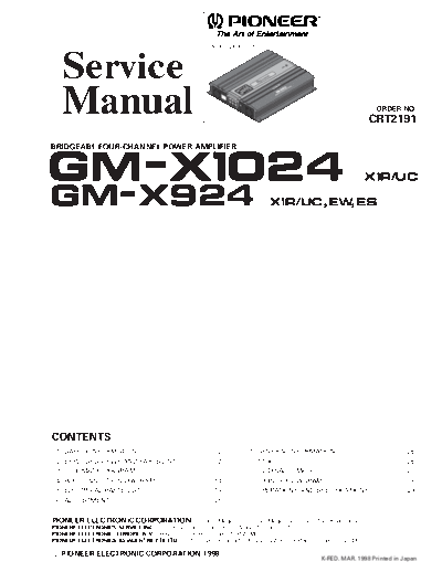
Image preview - the first page of the document

>> Download gm-x1024_gm-x924_723 documenatation <<
Text preview - extract from the document
                                                                     GM-X1024/X1R/UC


   Service
   Manual                                                                                                                                        ORDER NO.
                                                                                                                                             CRT2191

BRIDGEABL FOUR-CHANNEL POWER AMPLIFIER


GM-X1024                                                                                                                                   X1R/UC

GM-X924                                                                                    X1R/UC,EW,ES


CONTENTS
 1.   SAFETY INFORMATION ............................................2           7. GENERAL INFORMATION .......................................26
 2.   EXPLODED VIEWS AND PARTS LIST .......................2                        7.1 IC ........................................................................26
 3.   SCHEMATIC DIAGRAM .............................................8              7.2 DISASSEMBLY ...................................................27
 4.   PCB CONNECTION DIAGRAM ................................14                     7.3 BLOCK DIAGRAM ..............................................28
 5.   ELECTRICAL PARTS LIST ........................................19           8. OPERATIONS AND SPECIFICATIONS.....................29
 6.   ADJUSTMENT..........................................................25


PIONEER ELECTRONIC CORPORATION                   4-1, Meguro 1-Chome, Meguro-ku, Tokyo 153-8654, Japan
PIONEER ELECTRONICS SERVICE INC. P.O.Box 1760, Long Beach, CA 90801-1760 U.S.A.
PIONEER ELECTRONIC [EUROPE] N.V. Haven 1087 Keetberglaan 1, 9120 Melsele, Belgium
PIONEER ELECTRONICS ASIACENTRE PTE.LTD. 501 Orchard Road, #10-00, Lane Wheelock Place, Singapore 23880

C PIONEER ELECTRONIC CORPORATION 1998
                                                                                                                     K-FED. MAR. 1998 Printed in Japan
GM-X1024,GM-X924


1. SAFETY INFORMATION
CAUTION

This service manual is intended for qualified service technicians; it is not meant for the casual do-it-yourselfer.
Qualified technicians have the necessary test equipment and tools, and have been trained to properly and safely repair
complex products such as those covered by this manual.
Improperly performed repairs can adversely affect the safety and reliability of the product and may void the warranty.
If you are not qualified to perform the repair of this product properly and safely; you should not risk trying to do so and
refer the repair to a qualified service technician.

WARNING

Lead in solder used in this product is listed by the California Health and Welfare agency as a known reproductive
toxicant which may cause birth defects or other reproductive harm (California Health and Safety Code, Section
25249.5). When servicing or handling circuit boards and other components which contain lead in solder, avoid
unprotected skin contact with the solder. Also, when soldering do not inhale any smoke or fumes produced.


2. EXPLODED VIEWS AND PARTS LIST
2.1 PACKING


                                                                                              10


                                                                                              3       2
                                                                                                  5
                                                                                   4


        8                                                                                                             9

                                                                                                          6


                                                                                    9


                                    7
                                                                                                                    Fig. 1


2
                                                                               GM-X1024,GM-X924


NOTE:
- Parts marked by "*"are generally unavailable because they are not in our Master Spare Parts List.
- Screws adjacent to  mark on the product are used for disassembly.
(1) PACKING SECTION PARTS LIST

Mark No. Description                Part No.                 Mark No. Description                 Part No.
        1
◦ Jabse Service Manual Search 2024 ◦ Jabse Pravopis ◦ onTap.bg ◦ Other service manual resources online : Fixya ◦ eServiceinfo