Service Manuals, User Guides, Schematic Diagrams or docs for : Pioneer Audio CT-F650 hfe_pioneer_ct-f650_service_add_en
<< Back | HomeMost service manuals and schematics are PDF files, so You will need Adobre Acrobat Reader to view : Acrobat Download Some of the files are DjVu format. Readers and resources available here : DjVu Resources
For the compressed files, most common are zip and rar. Please, extract files with Your favorite compression software ( WinZip, WinRAR ... ) before viewing. If a document has multiple parts, You should download all, before extracting.
Good luck. Repair on Your own risk. Make sure You know what You are doing.
Image preview - the first page of the document
>> Download hfe_pioneer_ct-f650_service_add_en documenatation <<
Text preview - extract from the document
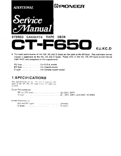
(v)rrroruEerr
STEREO CASSETTE TAPE DECK
GT-FEiSOKUK'D
. The basic performance of the KU, KC and D types are the sameas the HB type. This additional service
manual is applicable to the KU, KC and D types. Please refer to the HE, HB, HP types servicemanual
( A R T - 4 1 7 )w i t h e x c e p t i o no f t h i s s u p p l e m e n t s .
KU type ....For U.S.A. odel
m
KC type . . . .For Canada odel
m
D type . . . . For GeneralexDort model
1 .SPECIFICATIONS
The specifications for KU. KC and I) types are lhe
same as the HE. HR, IIP tlpes ercept for follouing
sections-
Power Requirements
KUandKCtype... ... AC 120V,60H2
D type . . . . . AC 120V, 220V,and 240Y,50160H2
Power Consumption
KU and KC types 19 watts
Dtypes........ 16 watts
2.CONTRAST OF MISCELLANEOUS PARTS
ASSE M B L Y
F"-
L
Symbol
I
HB type KU;yp"
P a r tN o .
I KC type
I R W X3 6 9 R W X3 s 7
]
I
R W X3 5 8 R W X3 5 8
TRANSFORMER
Symbol Description I
HB ,yp" KU ayp" KC type D type
iT1 Power transformer *tt_'_r? RTT196
l.ttll
swtTcHEs
Symbol Description
KU type
i S14 P o w e rs w i r c h
'i 513
L r n ev o r a g e( 2 p o s t i o n )
r L i n e v o r a g es e e c r o r ( 3 p o s r o n )
FUSE
a type KU type D type
R EK { 5 1
R E K0 4 8
O T H ER S
l
Symbol
, .,
T
c (
Ceramic apacitor 0.01)
Description
t KU type
R D G0 2 2
KC type
RD G , O 2 2
t
C a p a c i t o c o v e rl f o r C 1 )
r
C a p a c i t o r s l e e v eA REC I5O
R BM,O04
PACKING ATERIALS
M
Description
Ku type KC type
RHG 305 R H G3 O B RHG3O7 R H G3 0 9
O p e r a t i n gn s t r u c t i o n s
i RRB 111 R R B1 2 4 RRA,124 RRB,I]]
R EK { 5 1
F u s e0 . 5 A REKo48
3. SCHEMATIC DIAGRAMS, P.C.BOARD PATTERNS AND PA
3.1 SCHEMATIC IAGRAM
D
tcrol PA4005
c208 I
OO47 -
,ln
i?,i-T,I,""d
\(
se-
oNe
IR
OFFUl
2 S A 8 2 6 L N - Ro r S
or 2SA826-Ror S
q 2SAl127-R
ors
ND PARTS LIST
1.RESISTORS:
I n d i c a t e dn ! ) , % W ,,
i
M : M l ) , ( F ) : r 1 % ,( G
2. CAPACITORS:
I n d i c a t e di n c a p a c i t yi
I n d i c a t i o nw i t h o u t v
3. VOLTAGE
ll , D C v o l t a g e( V
The underlined iMicat
This is the basrc schem,
LEDTOI TLR-205 Ql39- l4l MOTOR c6o2
RXM- O55 o.,o.1
LEO703 TLG-205 2SA826LN-RorS
LED7O4 TLR- 2O5 or 254826- R or S
or 2SA'1127-Ror S
515 MOTOR
RSN-01 0
or RSN -O27
7 8 9
A
| __L
I
*:z:' .4 J,
' c s o l8 A 6 5 8
I Ht-T I l. l . 3 4 s 6 ' 10 1, 1? rr 14 15 | |
l
I ^""*:l:l l
ca2-o4sl l
t t t t t t t t t t l|t t t |t t | | | I I I I I I I | |
-4:::d lH
'[--1
-#- | | | l' r L 3 rB U 3 o
, L 5 ou 'G - - 5
E
-i" I
l[fr"
I l:'
,,r-
--il
| ', ,, ,. 14 15 16 17 ,, .o ,, ,, ,r"[--l
- l l lr, l l I
- iI - I I |
ll lu*,oI I I ll | I l l rl l I t I l I
,
,
r ^ r| 1 1 r o o e ^ ' ,' l f I | I | | I I I
I
B
-r j ,o
I c I I I I lcs:o4sl 2 4 5 6 ; 12 r3 14
lllll ll .Fd" ' | c 58 A 6 5 8
02 cH
| |
ll lll II F t f - T - l' ' .
lllll ll I.=l | |
]llll il l - , : , r - ' - lz D i o z x z - z @ 0 , 5 , I
z o l o ze 1 s 1 2SCr74oLN-RorS
llllllll
l
l ll l l l l l l
r I ll ll | I EJ\Prr
:.--*;;E
l ||| | l| t
| t
l|||l ,|RESTSToRS:
IlllllI
tndicated in !t,'/,W, t5%toleranceunlessotherwisenoted k : k.,
] | I | | I | |
M : M o , ( F r 1 % , ( : t 2 % , ( Kr)1 0 % r o r e r a n c e
:) G) : POWER SLjPH.Y CIRCU FOR CANADA MODEL
]l I ll ll I
i|l|ll
llIllll| 2cAPAcrroRS
| | 1t || | tndicatedrncapacity(pF)/vottage(V) untessotherwisenotedp pF
tndication without voltage is 5OV excer)t electrolytic capacitor
I I lI | | |
]-fTTt- | | 3voLrAGE
llll ll
| | + | | | T_],DC v o l t a s e V ) a t n o i n p u ts r s n a l
(
lll'l I I
llll ll 4oTHERS
l?lll | | @:Adjust,nspo,nt
\
if I I I
,
| | I |
| |
| I
T h e - 4 i ,m a r kf o u n d n s o m e o m p o n e l )ta r t sn d i c a t eb e r m
portance of
o
the safety
c
factor of
n i
the srart Therefore,
ts
when replacing,
c
be sure to use parts of identrcal desrgnation
| | | | | |
IIt| |I
Il ll l|l l l |
i
lllll ll sw'rcHES
,llll sr:REc/p.BSELECIoR nLAvBACK-REc
rlll ll
sz:DoLBYNR gf-o"
'-- ll
l l | | s3:rApESELEcroR(MEraL) qll- oN
-ApE
I* | | s4: s E L E C T o R ( F ec r )
- oFF - oN
l; | | ss:-aPESELECToR(croz) oFF-oN
-;ff I I s6: REC
MUrE qlr - oN
:- I ll s7,B:LrNE/MrcsELEcroR LINE-Mrc
H' I ll se:PLAY err*oN
I ll slo:REC oFF-oN
o I | | st:FASr oFF-oN
I ll t2:PMS oFF-oN
I ll s4:PowER oFF-oN
i ll tl5:MoroR oFF-oN
l|-
-he undertined
indicates switch
the position.
I I I
----1---l
ttl
tt
ll
I lhis is the basic schematic dragram, but the actual circurt may vary
D
I
12 I due to improvements rn design.
:;l
205
I
7 8 9
3 . 2 C O N N E C T I OD I A G R A M
N
|-
I 'AFs
f()
)aY
◦ Jabse Service Manual Search 2026 ◦ Jabse Pravopis ◦ onTap.bg ◦ Other service manual resources online : Fixya ◦ eServiceinfo