Service Manuals, User Guides, Schematic Diagrams or docs for : Pioneer Audio CX-680 hfe_pioneer_cx-680_service_en

<< Back | Home

Most service manuals and schematics are PDF files, so You will need Adobre Acrobat Reader to view : Acrobat Download Some of the files are DjVu format. Readers and resources available here : DjVu Resources
For the compressed files, most common are zip and rar. Please, extract files with Your favorite compression software ( WinZip, WinRAR ... ) before viewing. If a document has multiple parts, You should download all, before extracting.
Good luck. Repair on Your own risk. Make sure You know what You are doing.


Image preview - the first page of the document
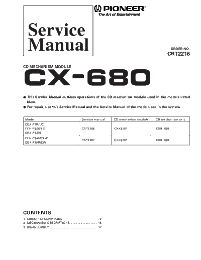
hfe_pioneer_cx-680_service_en


>> Download hfe_pioneer_cx-680_service_en documenatation <<

Text preview - extract from the document
    Service
    Manual                                                                                                     ORDER NO.
                                                                                                           CRT2216

CD MECHANISM MODULE


CX-680
-   This Service Manual outlines operations of the CD mechanism module used in the models listed
    blow.
-   For repair, use this Service Manual and the Service Manual of the model used in the system.


 Model                                                  Service manual         CD mechanism module   CD mechanism unit
 DEX-P1R/UC
 DEH-P946/ES                                            CRT2206                CXK5101               CXB1699
 DEX-P1/ES
 DEH-P945R/EW
                                                        CRT2207                CXK5101               CXB1699
 DEX-P99R/EW


CONTENTS
1. CIRCUIT DESCRIPTIONS ........................................... 2
2. MECHANISM DESCRIPTIONS ................................. 15
3. DISASSEMBLY .......................................................... 17
CX-680


1. CIRCUIT DESCRIPTIONS
1.1 Preamplifier (UPC2572GS: IC101)
The preamplifier processes pickup output signals to         EFM-IN 1                                        EFM comparator           FE
                                                                                                                                               38 FE-BAL
                                                                                                RF                                   BAL
                                                                                                                 HPF
generate signals to be sent to the servo, demodula-                                          envelope
                                                          AGC-OUT 2           AGC                                                    TE        37 TE-BAL
tor, and controller. The preamplifier with built-in                                                                                  BAL

                                                             C AGC 3      Detection                                                            36 ASY
photodetector converts signals from the pickup into                                                  Vcc
                                                                                                                               X12


intermediate voltage in the pickup. Then, addition is         RF-IN 4                                                                          35 EFM-OUT

made in the RF amplifier (IC101) to obtain RF, FE, TE,      RF-OUT 5                                                                           34 C.DEF
                                                                                                                   Peak
and TE zero cross signals. The system consists of the                                    DEFECT circuit
                                                                RF- 6                                                                          33 DEFECT
UPC2572GS and other components explained below.                                                                   Bottom       DC shift
                                                              C1.3T 7                                                                          32 RFOK
The system uses a single power source (+5 V). There-
fore, the reference voltage of IC101 and the reference        C2.3T 8                               Peak
                                                                                                                       Mirror circuit
                                                                                                                                               31 MIRR
                                                                                                                                        120k
voltage of the power unit and servo circuit are REFO           Vcc 9                                                                           30 3T-OUT
                                                                                                  Bottom
(+2.5 V). REFO is obtained from REFOUT of servo LSI              A 10                                             DC shift                     29 C.FE
(IC201: UPD63702GF) via a buffer, and is output from
                                                                 C 11                        3T detection    Phase detection    X3             28 FE-OUT
Pin 19 of IC101. This REFO is used as reference for all
                                                                 B 12                         FE BAL                                           27 FE-
measurements.                                                                                Control
                                                                 D 13                                                                          26 GND
Note: Do NOT short-circuit REFO and GND during
      measurement.                                               F 14                                                                          25 TE-
                                                                                                    FE BAL
                                                                 E 15                             Control                                      24 TE-OUT1

                                                                PD 16                                                                X2        23 TE-OUT2
                                                                                          Vcc
                                                                LD 17                                                                          22 DET-IN
                                                                          APC

                                                             LDON 18                                                                           21 DET-OUT

                                                          VREF-OUT 19                                                                          20 VREF-IN


                                                                         Fig. 1 Block Diagram of UPC2572GS


1) Automatic Power Control (APC) circuit
                                                                         Pickup unit
Laser diode has negative temperature characteristics                                                                         UPC2572GS
                                                                         Vcc (5V)
with great optical output when the diode is driven                                                                         2.5V

with constant current. Therefore, current must be                                       Vr
                                                                                                   R112
                                                                                                             16k
                                                                                                   2.2k PD
controlled by a monitor diode to ensure constant out-                                         5           16
put. Thus functions the APC circuit. LD current can be                   LD             MD
obtained by measuring the voltage between LD1 and
                                                                              15                                                     150k
                                                                                                   C104    1k
GND. The current value is approximately 35 mA.                                        Q101                                                         1k
                                                                                      2SD1664      0.33


◦ Jabse Service Manual Search 2024 ◦ Jabse PravopisonTap.bg ◦ Other service manual resources online : FixyaeServiceinfo