Service Manuals, User Guides, Schematic Diagrams or docs for : Pioneer Audio RG-9 rg_9_arp_054_0_110
<< Back | HomeMost service manuals and schematics are PDF files, so You will need Adobre Acrobat Reader to view : Acrobat Download Some of the files are DjVu format. Readers and resources available here : DjVu Resources
For the compressed files, most common are zip and rar. Please, extract files with Your favorite compression software ( WinZip, WinRAR ... ) before viewing. If a document has multiple parts, You should download all, before extracting.
Good luck. Repair on Your own risk. Make sure You know what You are doing.
Image preview - the first page of the document
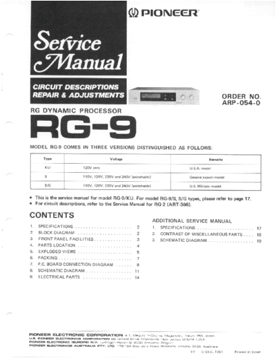
>> Download rg_9_arp_054_0_110 documenatation <<
Text preview - extract from the document
() rrtoNeerl"
ORDERNO.
ARP-O54-O
RG DYNAMIC PROCESSOR
FIGi-9
MODEL RG-g COMESIN THREE VERSIONSDISTINGUISHED FOLLOWS:
AS
Type VoltalF Ramark3
KU 120V only U.S.A.model
1lOV , 12OV 22OV and 240V (switchable
, I Generalexpon model
l1OV, 12OV 22OV and 240V (switchable)
, U.S. Military mod6l
. This is the servicemanualfor model RG-9/KU. For model RG-9/S,S/G types. pleaserefer to page17.
r For circuit descriptions,
refer to the ServiceManualfor RG-2 (ART-366).
CONTENTS
ADDITIONALSERVICEMANUAL
1 . S P E C | F | C A T | O N .S . .
. . l . s P E c f F f c A T t o.N.s .
. . ........ 17
2. B L O C KD I A G R A M 2. C O N T R A S T F M I S C E L L A N E O UP A R T S. . . . 1 8
O S
3, F R O N T A N E LF A C I L I T I E S
P 2 3. SCHEMATTC AGRAMDT ......... 19
4. PARTS LOCATION 4
5. E X P L O D E D I E W S. .
V 5
6. PACKING
7. P . C .B O A R DC O N N E C T I O N I A G R A M
D I
8. SCHEMATIC IAGRAM
D l'l
9. ELECTRICAL ARTS .
P 14
PIONEEFI ELECTFICINIC COFIFEIFATIG,N 4 I. Meeuno 1 chome, ^,4esu.o ku. Tokyo 15i3. Jep6n
U.B, FfCt\fEEFl E-ECTFIO IICA crE FrPCtEAnCt t 85 oxrord O.'ve, Moon6ch,e, New Je.sey O7O74, lJsA.
P|CNEEFT ELEG|TFIC|I\||C (EUF|I'FE N.W. Luihegen Beven S, 2o3O Anrwe.p, Bers,um
FrchrEEFf ELEc-rEo llc a(JtlrEALlA FiY. LtD. 17a 1a4 aat da.y Road, E|resde, v.ion,6 g195, auscn. 6
YP O DEC.98l
t P r i n t e di n l a p a n
1. SPECIFICATIONS
Processor
Section Miscellaneous
Ma xi mum ut put V olt a g e
O . . 6 .5V P ow erR equi rements A C 120V, 60Hz
( 1k H z ,T . H . D . O . 5 o /R 1 : 4 7 k C 2D Y N A Ml C
: o , PowerConsumption 10W
E X P A N S I O N :6 d B )
1 Dimensions 4 2 0 ( W ) 9 9 ( H )x 3 3 6 ( D )m m
x
To ta l Har m onic t or ti o n
Dis . 0 . 05% 16-9116(W ) 3-718(Hx 13-1l4lD)in
x )
( O u t p u t1 V ,l k H z ,D Y N A M I C X P A N S I O N : 1 6 d 8 )
: E W ei ght(w i thoutpackage) 4.4k9(9 lb 11ozl
Dynamic xpansion
E 4 , 7, 1 0 , 1 3 1 6 d B
Furnished Parts
Gain
Connectioncordwithpinplugs .....2
DYNAMIC Operati ngnstructi ons
i 1
4dB 7dB 10 d B 13dB 16 d B
EXPANSION
U p w a rdG ain + 2 d B +4dB +6dB +8dB +1 dB
o
Downward -2dB -3dB -4dB -5dB -dB
Gain NOTE:
Specifications and the design subject to possible modification
l mp u l se Res pons e without notice due to improvements.
AttackTime .. .0.3msec
Re l easT im e
e 1 2 0 msec
fn p u t l m pedanc e 5 0 k O (2 OH z 2 0 kH z)
to
Ou tp u t l m pedanc e 3 0 0 S,(l kH z)
Re si d ual Nois e 1 0pV
( l H F A , D Y N A M I CE X P A N S I O N1 6 d B )
:
S i g n ato Nois eRat io( lH F A , Sh o rtc i rc u i te d ,
l
D Y N A M C E X P A N S I O N1 6 d B )
l : 1 0 0 d 8( a t 1 V )
1 1 6 d B( a t 6 . 5 V )
2. BLOCK DIAGRAM
RG DETECTOR IRCUIT
C D Y N A M I CE X P A N S I O NM E T E R
l-MAxl |?oel @ ltodBl lT3l [6d-d
otrotrtrtrootrtrtroo trtrtrtrotro
Lch
PROCESSOR
trtroootroootrotroQtrBtrotrtr
IN P U T
3l6mV 16t514t3t2illo9
OUTPUT t2345678
IV
TAPE
REC GAIN CONTROLAMP TUBEDRIVER
3l6mV
PLAY
lv
Rch
PROCESSOR
ooN RELAY DRIVERCIRCUIT
h s2-3 "T: i8ln$o"r." ur{swrrcHEo
AC t20V
TAPE 60 Hz
MOttllTOR
METER
swrTcHEs
POWER
S I TAPE MONITOR ON - OFF
s2 PROCESSOR S-OFF
s3 DYNAMTCEXPANSTON 4de-7atB-tOdB-t3d8-t5dB
54 POWER ON -OFF
Thc und.rlin.d indicotca tha !uitch po3ition
2
3. FRONT PANEL FACILITIES
e POWER
SWTTCH @ T A P E M O N I T o RI N D I c A T o R
Power is suppliedto the model RG-9 when this switch is This comeson when the tape monitor switch is depressed.
depressed. The power indicator comeson as soon as the
power is supplied. @ TAPE MONTTOR
SWTTCH
Depress this switch to monitor the soundon the tapeas it
@ PowER
rNDrcAToR is beingrecorded when playingback a tape usinga tape
or
This comes on as soon as the RG-9's power switch is deck connected to the RG-9's TAPE jacks. (The tape
setto ON to indicatethat power is beingsupplied. moni tor i ndi cator
comeson.) S et the sw it cht o O FF when
not in use.
EXPANSTON
) DYNAMTC METER
This meter allows you to read out the gain boost with @ DYNAMIcEXPANSIoN ELEcToR
S
(Seeaddi ti onal
r es pec tt o t he i n p u t s i g n a li n d e c i b e l s . This selector selects maximum gain boost value with
des c r ipt ion p a g e ).
on 6 respect to the input level, i.e.: ratio of gain increase
between large input signal and small ipput signal.Max-
@ D Y N A M I CE X P A N S I o NN D I c A T o R S
I
imum gain boost increases as the selector is turned
T he 4dB , 7dB , 1 0 d 8 , 1 3 d 8 , 1 6 d B i n d i c a torsl i ght up
clockwise. Set the selector to the most desirable position
in accordancewith the positionof the dynamicexpansion w h i l e l i s t e n i n gt o t h e r e p r o d u c e ds o u n d .
selector.
* Dynamic Expansion
@ PRocESsoR
SWITcH Dynamic expansion is defined as the sum of the downward
Depress this switch (ON) to producean expansion expansion (where small inputs are expanded down) and upward
effect
expnsion (where large inputs are expandedup).
wit h t he s igna l s d fro m th e P R OC ES SOR P U Tj acks.
fe IN
T he dy nam ic e x p a n s i o ni n d i c a to r w i l l c o m e or, and
signals featuringan expansion effect only will be fed out ) | N P U TL E V E LC O N T R O L
f r om t he m od e l R G-9 ' sO U T PU Tj a c k s .In the OFF posi - U se thi s control to adj ustthe i nput l evelat which t he
t ion, t he RG -9c i rc u i try i s b y p a s s e d . h i s p o si ti onal l ow s
T expansion effect is initiated.Clockwise rotation increases
for instantcomparison between expanded
the and the un- the expansion with respect smallsignallevels
to (increases
processed signals. expansion sensitivity). Adjust the control for desired
NOTE: effect according programsource.
to
When the RG-9's power switch is set to the OFF position and
the processor switch is also set fo OFF, the signal which has
bypassed the processor circuitry is nnde available at the
OUTPUT jacks. There will, however, be no output if the input
level control is set to the '0' position. Make sure that this control
I'sset to the'lO' position.
4. PARTS LOCATION
NOTES:
c Parts without part number cannot be supplied.
o The [y marh found on some component parts indicates the importance of
the
safety factor of the part. Therefore, when replacing, be sure to use parts of identical
designation.
r Front PanelView
Knob(DYNAMIC XPANSIONI
E
Front panel assembly AAB-291
ANM-121
Pushknob A (POWER)__=___== I fh
''--t f+--Knob
' LEVEL)
sNpUr
'/ AAB-291
AAD-178 | |
Stur$
Pushknob B (TAPEMONITOR)
AAD.179
Push knob B (PROCESSOR)
AAD-179
r Front View with PanelRemoved
** Slide rotary switch
(DYNAMIC EXPANSION}
ASE.115
[ ** eusnswitch(POWER] * Variableresistor
ASG-215 ( I N P U TL E V E L }
ACV-155
* Flourescent
indicatortube
P u s hs w i t c h ( T A P E M O N I T O R )
AAV.OO3 ASG-216
** Pushswitch (PROCESSOR)
ASG-216
I Top View
A * Po*"r transformer
ATT.588
Processorassembly
GWM.134
Switch assembly
GWS-186
Dynamic expansion
meter assembly g
GWV-101
&
*
r RearPanelView
Bonnet case
ANE-376
A AC socket(AC OUTLET)
AKP-038
Strain relief
AEC-327
4P Pinjack A AC power cord
AKB.O54 ADG-052
5. EXPLODED VIEW
NO?8S..
. Pdrts uithout port number connot be supplied.
. The A morh found on some component ports indicates the importance of the
safety factor of the port. Thercfore, when ieplqcing, be sure to use parts of identical
desar.otion"
. For tour Patts Stoch Control, the fast mouing items are indicated uith the marhs
** ond ,-
,* GENERALLY MOVES FASTER THAN *.
This classificotion shall be ddiulted by each dbtributor becouse it depende on model
numbe\ temperotute, hamidity, etc,
Parts Li3t
Mark No. Part No. Description Mark No. Part No. Description
1. ANE-376 Bonnetcase 51. Rubber B
2. VCT30PO60FZK Screw 52. Center frame
3. ANM-121 Front panelassembty il. Panel stay
4. VCZ30PO6OFMC Screw 55. Rubber A
5. AAB-291 Knob
56. LED holder
6. AAD-178 Pushknob A 57. Rear panel
7. AAD-179 Pushknob B 58. Bottom plate
8. ABN-024 Nut
A * 9. ATT-588 power transformer (120V)
a 10. AKP-O38 AC socket(AC OUTLET)
A 11. ADG-OS2 AC powercord
12. AEC-327 Strain retief
13. ACE-351 Foot assembly
14. VBZ3OP1OOFZK Screw
15. VTZ40P080FMC Screw
16. VMZ30P060FMC Screw
17. VTZ4OP160FMC Screw
18. VBZ30P060FMC Screw
19. ABA-115 Screw
20. MTZ3OP1OOFZK Screw
21. WA45F125KO50 Waher
22. GWX-3OS Pinjackassembty
23. GWX-36 LED asembty
24. GW9186 Switch assembly
25. GWV-lOl Dynamicexpansion meter
assembly
26. GWX-307 LED assembty
27. GWM-134 Processorassembly
1 2 3 L-
,e-,_,
6_)
f8
--
7At 3 Y
N
rr-lZrU
6. PACKING
PartsList
Mark No. Part No. Description
1. AHA-310 Side pad
2. AR8463 Operati ng instructions
3. ADE.OOs Connection cord
4. AHE.OlO Packing case
7. P.C. BOARD CONNECTIONDIAGRAM
I 3
AS
PROCESSOR
GWM-t34
422 92O
Qt5 Ola 06
PINJACKAss'y o240r4 0rz oo oto ort d2
A GWX-305
B
c
DVI|AMICEXmNS|or{ METER A$l
-l' 2 3
I
4 5 6
Ass'y
IOCESSOR
-
GWM t34
or 05 0r9 Q3
06 Q26 Q2t Or5 Oil Q13
04 02 025 Q29 Qi7 q9 07 O23 Q33 032
I o--l|--
o29 ,rPcit558c-P | | c5! 0.047
ar r00t( orirJM4at8ox R , , er , ( , . 2 r l l
| |
Ri 2?u
i49 too(
,,.,2, -"';'\ -lIf! -ut'"**
rer6 - *;
: #x. *ffi l:l | .--
"-- |
F'.-
*Ife_ ifi6'o" "n,r,," I:l | I _^^ __!."",1
'ff'
6,?* iffi7;i.-.*,...,r",.... [:l I| **)
"' *.!4 -",-o*- jrij]* lo'"'
'k*,di."-""$hn;
;r;a
::,qi
◦ Jabse Service Manual Search 2026 ◦ Jabse Pravopis ◦ onTap.bg ◦ Other service manual resources online : Fixya ◦ eServiceinfo