Service Manuals, User Guides, Schematic Diagrams or docs for : Pioneer Audio XC-HM81-K pioneer_x-hm81_x-hm71-k_s_rrv4322
<< Back | HomeMost service manuals and schematics are PDF files, so You will need Adobre Acrobat Reader to view : Acrobat Download Some of the files are DjVu format. Readers and resources available here : DjVu Resources
For the compressed files, most common are zip and rar. Please, extract files with Your favorite compression software ( WinZip, WinRAR ... ) before viewing. If a document has multiple parts, You should download all, before extracting.
Good luck. Repair on Your own risk. Make sure You know what You are doing.
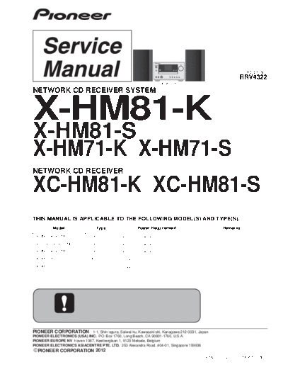
Image preview - the first page of the document

>> Download pioneer_x-hm81_x-hm71-k_s_rrv4322 documenatation <<
Text preview - extract from the document
                                                                                                       ORDER NO.
                                                                                                     RRV4322
                                                                X-HM81-K

NETWORK CD RECEIVER SYSTEM


X-HM81-K
X-HM81-S
X-HM71-K X-HM71-S
NETWORK CD RECEIVER

XC-HM81-K XC-HM81-S
THIS MANUAL IS APPLICABLE TO THE FOLLOWING MODEL(S) AND TYPE(S).
         Model                   Type                 Power Requirement                     Remarks

 X-HM81-K, X-HM81-S        SYXE8           AC 220 V to 240 V

 XC-HM81-K, XC-HM81-S      SYXE8           AC 220 V to 240 V

 X-HM71-K, X-HM71-S        SYXE8           AC 220 V to 240 V

 X-HM71-K                  CXE             AC 120 V

 X-HM71-S                  AXQ5            AC 220 V


PIONEER CORPORATION 1-1, Shin-ogura, Saiwai-ku, Kawasaki-shi, Kanagawa 212-0031, Japan
PIONEER ELECTRONICS (USA) INC. P.O. Box 1760, Long Beach, CA 90801-1760, U.S.A.
PIONEER EUROPE NV Haven 1087, Keetberglaan 1, 9120 Melsele, Belgium
PIONEER ELECTRONICS ASIACENTRE PTE. LTD. 253 Alexandra Road, #04-01, Singapore 159936
  PIONEER CORPORATION 2012
                                                                                    K-MZV AUG. 2012 Printed in Japan
                  1                                      2                          3                           4

    SAFETY INFORMATION

A


    This service manual is intended for qualified service technicians; it is not meant for the casual do-it-
    yourselfer. Qualified technicians have the necessary test equipment and tools, and have been trained
    to properly and safely repair complex products such as those covered by this manual.
    Improperly performed repairs can adversely affect the safety and reliability of the product and may
    void the warranty. If you are not qualified to perform the repair of this product properly and safely, you
    should not risk trying to do so and refer the repair to a qualified service technician.

    WARNING
B   This product may contain a chemical known to the State of California to cause cancer, or birth defects or other reproductive
    harm.
                                                                         Health & Safety Code Section 25249.6 - Proposition 65


    Laser Pickup specifications and Laser characteristics
         For CD       Wave length (typ) : 790 nm
                      Operation output : 3 mW CW, Class 1
                      Maximum output : Class 1 (Under fault condition)


C


    LABEL CHECK
D

      SYXE8 model


                                                                                        AXQ5 model
                                                             CXE model


E


F


     2                                                                   X-HM81-K
                  1                                      2                          3                           4
                  5                                                6                                                7                                                8

CONTENTS
 SAFETY INFORMATION.......................................................................................................................................................... 2
1. SERVICE PRECAUTIONS .................................................................................................................................................... 4
   1.1 NOTES ON SOLDERING ............................................................................................................................................... 4                  A
   1.2 WHEN REPLACING MECHA ......................................................................................................................................... 4
   1.3 WHEN REPLACING CR870 (Module including BCO Assy) ........................................................................................... 4
2. SPECIFICATIONS................................................................................................................................................................. 5
3. BASIC ITEMS FOR SERVICE .............................................................................................................................................. 6
   3.1 CHECK POINTS AFTER SERVICING ........................................................................................................................... 6
   3.2 JIGS LIST ....................................................................................................................................................................... 6
   3.3 PCB LOCATIONS ........................................................................................................................................................... 7
4. BLOCK DIAGRAM .............................................................................................................................................................. 10
   4.1 OVERALL WIRING DIAGRAM ..................................................................................................................................... 10
   4.2 OVERALL BLOCK DIAGRAM....................................................................................................................................... 12
   4.3 POWER SUPPLY BLOCK DIAGRAM........................................................................................................................... 14
5. DIAGNOSIS ........................................................................................................................................................................ 16     B
   5.1 TROUBLESHOOTING.................................................................................................................................................. 16
   5.2 PROTECTION CIRCUIT............................................................................................................................................... 21
   5.3 POWER MANAGEMENT.............................................................................................................................................. 24
   5.4 CHECKING TERMINALS ............................................................................................................................................. 25
   5.5 IC INFORMATION ........................................................................................................................................................ 28
6. SERVICE MODE ................................................................................................................................................................. 31
   6.1 SERVICE MODE .......................................................................................................................................................... 31
   6.2 PROTECT CHECK MODE ........................................................................................................................................... 33
   6.3 CHECKING THE LCD .................................................................................................................................................. 35
   6.4 RDS CHARACTERS..................................................................................................................................................... 36
7. DISASSEMBLY ................................................................................................................................................................... 37
                                                                                                                                                                                             C
8. EACH SETTING AND ADJUSTMENT ................................................................................................................................ 45
   8.1 UPDATING OF THE FIRMWARE ................................................................................................................................. 45
   8.2 INITIAL SETTINGS....................................................................................................................................................... 51
9. EXPLODED VIEWS AND PARTS LIST............................................................................................................................... 52
   9.1 PACKING SECTION ..................................................................................................................................................... 52
   9.2 EXTERIOR SECTION .................................................................................................................................................. 54
   9.3 SPEAKER SECTION (S-HM81GB, S-HM81SA) .......................................................................................................... 58
   9.4 SPAEKER SECTION (S-HM71).................................................................................................................................... 59
10. SCHEMATIC DIAGRAM .................................................................................................................................................... 60
   10.1 CD ASSY .................................................................................................................................................................... 60
   10.2 TUNER and BT ASSYS.............................................................................................................................................. 62
   10.3 MAIN ASSY (1/3)........................................................................................................................................................ 64           D
   10.4 MAIN ASSY (2/3)........................................................................................................................................................ 66
   10.5 MAIN ASSY (3/3)........................................................................................................................................................ 68
   10.6 BCO ASSY (1/2) ......................................................................................................................................................... 70
   10.7 BCO ASSY (2/2) ......................................................................................................................................................... 72
   10.8 CNT1 ASSY................................................................................................................................................................ 74
   10.9 CNT2 ASSY................................................................................................................................................................ 76
   10.10 CNT3 ASSY.............................................................................................................................................................. 78
   10.11 F_AUX, F_USB, FRONT and KEY ASSYS .............................................................................................................. 80
   10.12 DOCKING ASSY ...................................................................................................................................................... 82
   10.13 POWER ASSY.......................................................................................................................................................... 84
   10.14 WAVEFORMS........................................................................................................................................................... 86
11. PCB CONNECTION DIAGRAM ........................................................................................................................................ 88                       E
   11.1 CD ASSY .................................................................................................................................................................... 88
   11.2 TUNER and BT ASSYS.............................................................................................................................................. 90
   11.3 MAIN ASSY ................................................................................................................................................................ 92
   11.4 BCO ASSY ................................................................................................................................................................. 96
   11.5 CNT1, CNT2 and CNT3 ASSYS................................................................................................................................. 98
   11.6 F_AUX, F_USB, FRONT, KEY and DOCKING ASSYS ............................................................................................ 102
   11.7 POWER ASSY.......................................................................................................................................................... 106
12. PCB PARTS LIST ............................................................................................................................................................ 108


                                                                                                                                                                                             F


                                                                                     X-HM81-K                                                                                         3
                  5                                                6                                                7                                                8
                1                                  2                                 3                               4

    1. SERVICE PRECAUTIONS
    1.1 NOTES ON SOLDERING
A
◦ Jabse Service Manual Search 2024 ◦ Jabse Pravopis ◦ onTap.bg ◦ Other service manual resources online : Fixya ◦ eServiceinfo