Service Manuals, User Guides, Schematic Diagrams or docs for : Pioneer DVD BDP-LX52 pioneer_bdp-lx52
<< Back | HomeMost service manuals and schematics are PDF files, so You will need Adobre Acrobat Reader to view : Acrobat Download Some of the files are DjVu format. Readers and resources available here : DjVu Resources
For the compressed files, most common are zip and rar. Please, extract files with Your favorite compression software ( WinZip, WinRAR ... ) before viewing. If a document has multiple parts, You should download all, before extracting.
Good luck. Repair on Your own risk. Make sure You know what You are doing.
Image preview - the first page of the document

>> Download pioneer_bdp-lx52 documenatation <<
Text preview - extract from the document
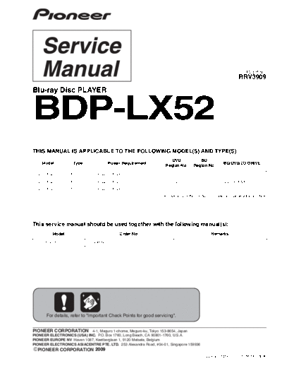
                                                                                                                    ORDER NO.
                                                                                                                 RRV3909
                                                                 BDP-LX52

Blu-ray Disc PLAYER


BDP-LX52
THIS MANUAL IS APPLICABLE TO THE FOLLOWING MODEL(S) AND TYPE(S).
                                                                      DVD               BD
    Model           Type              Power Requirement                                                 BD/DVD/CD DRIVE
                                                                   Region No.        Region No.

 BDP-LX52         YXJ5          AC 220 V to 240 V                        2                 B

 BDP-LX52         VXJ5          AC 220 V to 240 V                        2                 B           BDV-104-XA/XV/5*

 BDP-LX52         SXJ5          AC 220 V to 240 V                        5                 C
                                                               *The Drive assy of this product is subject to change without notice.


This service manual should be used together with the following manual(s):
          Model                              Order No.                                          Remarks

 BDP-320/YXJ5               RRV3899


       For details, refer to "Important Check Points for good servicing".


PIONEER CORPORATION 4-1, Meguro 1-chome, Meguro-ku, Tokyo 153-8654, Japan
PIONEER ELECTRONICS (USA) INC. P.O. Box 1760, Long Beach, CA 90801-1760, U.S.A.
PIONEER EUROPE NV Haven 1087, Keetberglaan 1, 9120 Melsele, Belgium
PIONEER ELECTRONICS ASIACENTRE PTE. LTD. 253 Alexandra Road, #04-01, Singapore 159936
  PIONEER CORPORATION 2009
                                                                                           T-ZZY-001 MAY 2009 Printed in Japan
                      1                                                2                                               3                                                4

    CONTENTS
        1. SERVICE PRECAUTIONS ....................................................................................................................................................2
A          1.1 NOTES ON REPLACING PARTS ...................................................................................................................................2
           1.2 NOTE ON REPLACING THE TRAY PANEL ...................................................................................................................3
        2. SPECIFICATIONS .................................................................................................................................................................3
           2.1 SPECIFICATIONS...........................................................................................................................................................3
           2.2 PANEL FACILITIES .........................................................................................................................................................4
        3. BASIC ITEMS FOR SERVICE...............................................................................................................................................7
           3.1 CHECK POINTS AFTER SERVICING............................................................................................................................7
           3.2 PCB LOCATIONS ...........................................................................................................................................................8
           3.3 JIGS LIST .......................................................................................................................................................................8
        4. DISASSEMBLY......................................................................................................................................................................9
        5. EXPLODED VIEWS AND PARTS LIST...............................................................................................................................18
           5.1 PACKING SECTION .....................................................................................................................................................18
B          5.2 EXTERIOR SECTION...................................................................................................................................................20
           5.3 FRONT PANEL SECTION ............................................................................................................................................22
        6. SCHEMATIC DIAGRAM ......................................................................................................................................................24
           6.1 SERVICE MAIN ASSY (1/12)(GUIDE PAGE) ...............................................................................................................24
           6.2 SERVICE MAIN ASSY (2/12)(GUIDE PAGE) ...............................................................................................................30
           6.3 SERVICE MAIN ASSY (3/12) .......................................................................................................................................36
           6.4 SERVICE MAIN ASSY (4/12) .......................................................................................................................................38
           6.5 SERVICE MAIN ASSY (5/12) .......................................................................................................................................40
           6.6 SERVICE MAIN ASSY (6/12) .......................................................................................................................................42
           6.7 SERVICE MAIN ASSY (7/12) .......................................................................................................................................44
           6.8 SERVICE MAIN ASSY (8/12) .......................................................................................................................................46
           6.9 SERVICE MAIN ASSY (9/12) .......................................................................................................................................48
C
           6.10 SERVICE MAIN ASSY (10/12) ...................................................................................................................................50
           6.11 SERVICE MAIN ASSY (11/12) ...................................................................................................................................52
           6.12 SERVICE MAIN ASSY (12/12) ...................................................................................................................................54
        7. PCB PARTS LIST ................................................................................................................................................................56


    1. SERVICE PRECAUTIONS
    1.1 NOTES ON REPLACING PARTS
    The part listed below is difficult to replace as a discrete component part.
    When the part listed in the table is defective, replace whole Assy.
D

                                         ASSY          PCB ASSY                                 Parts that is Difficult to Replace
                                         NAME           Part No. Ref No.                   FUNCTION                Part No.            Remarks
                                                                                                                   R8A34019BG-
                                                                       IC1001              Main u-com                          IC with BGA
                                                                                                                   RF4Z
                                                                IC2101,2201, DDR 128Mbit                           K4T1G084QE-
                                                                                                                               IC with BGA
                                       Service         VXX3356, 2301,2401    memory                                HCE6
                                      Main Assy        VXX3360
                                                                             DDR 512Mbit                           K4T51163QG-
                                                                IC3101,3201                                                    IC with BGA
                                                                             memory                                HCE6
                                                                                                                                       connector with very
                                                                       JA5001              HDMI connector AKP7225
E
                                                                                                                                       small solder pitch


F


    2                                                                                   BDP-LX52
                      1                                                2                                               3                                                4
                            5                                  6                                            7                           8

1.2 NOTE ON REPLACING THE TRAY PANEL
◦ Jabse Service Manual Search 2024 ◦ Jabse Pravopis ◦ onTap.bg ◦ Other service manual resources online : Fixya ◦ eServiceinfo