Service Manuals, User Guides, Schematic Diagrams or docs for : Pioneer PDP PDP-4270 ARP3391_PDP-4270XD(PROVISIONAL-part2)

<< Back | Home

Most service manuals and schematics are PDF files, so You will need Adobre Acrobat Reader to view : Acrobat Download Some of the files are DjVu format. Readers and resources available here : DjVu Resources
For the compressed files, most common are zip and rar. Please, extract files with Your favorite compression software ( WinZip, WinRAR ... ) before viewing. If a document has multiple parts, You should download all, before extracting.
Good luck. Repair on Your own risk. Make sure You know what You are doing.


Image preview - the first page of the document
ARP3391_PDP-4270XD(PROVISIONAL-part2)


>> Download ARP3391_PDP-4270XD(PROVISIONAL-part2) documenatation <<

Text preview - extract from the document
                5                             6                                       7                                       8


                                                                                                                                                        A
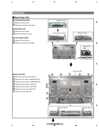
Disassembly

1 Rear Case (427)
    Function button panel                                             SIDE KEY Assy
1    Remove the two screws.
2    Remove the function button panel.

    Side input cover
3    Remove the two screws.
                                                                                                                                                        B
                                                              Function button panel                        Side input cover
4    Remove the side input cover.
                                                      1                               1                3                      3
    Power button holder
5    Remove the two screws.                                           2                                                4
6    Remove the power button holder.

                                                                                                                       Power button
                                                                                                                       holder

                                                                                                                                      5
                                                                                                                          5                             C


                                                                                                                                  6


                                                                                                  Rear case (427)

    Rear case (427)                                           5               5               3              5                        5                 D
                                                      3                                                                                       3
1    Remove the two protection sheets C.
2    Remove the 23 screws. (AMZ30P060FTB)
                                                                          2                                      2
3    Remove the nine screws. (TBZ40P080FTB)
                                                                                                                                              3
4    Remove the four screws. (ABA1332)            3           2                                                                       2
5    Remove the four screws. (ABA1353)            4
6    Remove the one screw. (ABA1341)                          2           2                                      2                    2       4
7    Remove the rear case (427).                                                                                                              3
                                                  3           2                               7                                       2
                                                                                                                                                        E
                                                                                  2       2       6     2
                                                                                                                                              3
                                                  3                   2                                                2
                                                          4                                                                               4
                                                      2                                                                                       2
                                                                      Protection sheet C                             Protection sheet C
                                                                          1                                           1
                                                          2       2                                                           2 2
                                                                              2                                  2
                                                                                                                                                        F


                                                          PDP-4270XD                                                                              101
                 5                            6                                       7                                           8
                  1                                      2                                    3                                       4


A
      2 Access to PCB Assys
          SIDE Assy                                                                 Side input shield                             SIDE Assy
      1    Remove the four screws.
                                                                                    2
      2    Remove the two screws.                                             1               1
      3    Remove the three screws.
      4    Remove the side input panel (E).


          42 X DRIVE Assy
                                                                     Function button shield   SIDE KEY Assy                    Side input panel (E)
B     1    Remove the two screws.
      2    Remove the side input shield with PCB.                                                                          1                 1
                                                                          1         2              1                  1                               1
          42 Y DRIVE Assy
      1    Remove the two screws.
                                                                                                                          2 3          4          2


◦ Jabse Service Manual Search 2024 ◦ Jabse PravopisonTap.bg ◦ Other service manual resources online : FixyaeServiceinfo