Service Manuals, User Guides, Schematic Diagrams or docs for : Roland Boss DR-55 Service Manual
<< Back | HomeMost service manuals and schematics are PDF files, so You will need Adobre Acrobat Reader to view : Acrobat Download Some of the files are DjVu format. Readers and resources available here : DjVu Resources
For the compressed files, most common are zip and rar. Please, extract files with Your favorite compression software ( WinZip, WinRAR ... ) before viewing. If a document has multiple parts, You should download all, before extracting.
Good luck. Repair on Your own risk. Make sure You know what You are doing.
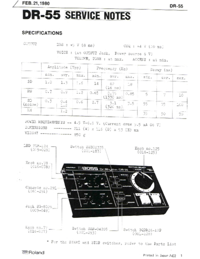
Image preview - the first page of the document

>> Download Boss DR-55 Service Manual documenatation <<
Text preview - extract from the document
FEB. 21,1980

     1    RS FLIP FLOP (2/4 IC3)

(a) PLAY Mode
When the START switch S5 is turned ON, the Q cutput goes to H and trig-
gers the Clock Generator (2). Mhen the STOP switch S6 is turned ON, the
Q output goes to L and the Clock Generator stops oscillation. At   this
time, the Q output goes to H and resets the Binary Counter (5)

(b) WRITE Mode
The Q output goes to H when S5 is turned ON, and goes to L when S6   is
turned ON. This condition is written in the Memory IC1 as a data.

     2    CLOCK GENERATOR (2/4 IC3)

The frequency of this oscillator is controlled with TEMPO VR-5.      This
oscillator functions in PLAY mode only, and feeds clock pulses to    the
Counter (5)

     3    SCHIMITT TRIGGER (Q15, 17, 18)

This circuit functions in WRITE mode only. The collector of Ql5 goes
H when either the START switch S5 or the STOP switch S6 is turned   ON,
and goes to L when the switch set to ON is turned OFF.

     4    DELAY CIRCUIT (Q16)

The output from the Schmitt circuit (3) is intergrated, and fed to the
base of Q16. Then the signal is trimmed to square wave at collector of
Ql6. This output signal is differentiated and becomes pulses, and then
is applied to the R/~W terminal of IC1.
The two pulses lag a little behind edges of Scmitt (3) output pulse.

     5    DUAL BINARY COUNTER (IC2)

This circuit counts pulses from the clock generator (2)    in PLAY mode,
and counts pulses from the Schmitt trigger (3) in WRITE mode, and then
outputs binary-coded signals from the terminals Ql-Q5; Ql-Q4 denote 16
steps composing each rhythm. Signal from Q5 is applied to A7 only when
the VARIATION switch is set to AB.
To the terminal A7, the L level voltage is given when the switch is set
to A and H when switch is set to B.
                                                                     DR-5
                                                                     5

     6    256 x 4 BIT CMOS MEMORY (IC1)

Reading/writing from/to this memory is as described below.
The upper 3 bits designate rhythms 1-8, the next one bit
designates
VARIATION A and B, and. the lower 4 bits 16 steps in one rhythm.
In PLAY mode, the terminal CE2 is connected. to the Clock
generator
output. The memory functions only when the clock is H, and
outputs
H's or L's from DO 1-4.
(When the clock is L, DO 1-4 becomes high impedance.)

In WRITE mode, when the terminal R/~W becomes L,a data from the
flip
flop is written in one of DI 1-4 via Sl.A previously stored data
is
rewritten from DO via R61-R64 to the remaining three DI's.

The Vcc of this rnemory chip is directly connected to the dry
cells
regardless of power switch positions, since the chip draws only
a
very slight idling current during stand-by. As a result, the
data
is guaranteed to be stored as long as the dry cells maintain
voltage
value higher than a specified. level.
The capacitor C39 (22 mfd.) connected to the terminal Vcc can
substi-
tute for the dry cells by its charge for several minutes when
the
cells are absent during replacement.

     7    VOlCE GENERATOR (Ql, 2, 3, 7, 8, 9, 10, ll)

BD, SD and RS are triggered by pulses from the respective DO's. HI
HAT is triggered by pulses from the counter IC2 or the Clock gen-
erator IC3 by every step or every other step.

     8    ACCENT (Q3)

Each sound source output is mixed and outputted through the resis-
tor network in which Q3 is connected in parallel.When ACCENT pulse
is outputted from DO l, Q3 turned ON, and in this ON period the
signal amplitude increases. The DO l pulse can be externally out-
putted through the CSQ jack.When this jack is enga.ged,
however,the
ACCENT function of the DR-55 proper becomes invalid.
◦ Jabse Service Manual Search 2024 ◦ Jabse Pravopis ◦ onTap.bg ◦ Other service manual resources online : Fixya ◦ eServiceinfo