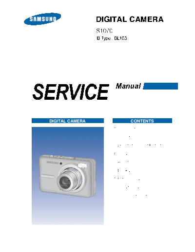
Service Manuals, User Guides, Schematic Diagrams or docs for : Samsung Cameras S1070_CS_ENG_ver3
<< Back | HomeMost service manuals and schematics are PDF files, so You will need Adobre Acrobat Reader to view : Acrobat Download Some of the files are DjVu format. Readers and resources available here : DjVu Resources
For the compressed files, most common are zip and rar. Please, extract files with Your favorite compression software ( WinZip, WinRAR ... ) before viewing. If a document has multiple parts, You should download all, before extracting.
Good luck. Repair on Your own risk. Make sure You know what You are doing.
Image preview - the first page of the document

>> Download S1070_CS_ENG_ver3 documenatation <<
Text preview - extract from the document
                  DIGITAL CAMERA

                  B-Type : BL103


SERVICE
                          Manual


 DIGITAL CAMERA                      CONTENTS
                         1. Specification

                         2. Installation

                         3. Exploded view and Part list

                         4. Firmware

                         5. Adjustment

                         6. Block Diagram

                         7. Pattern Diagram

                         8. Circuit Diagram

                         9. Service Information
                                 CONTENTS

. SPECIFICATION
    1. CAMERA SPECIFICATION ................................................................................. 4
    2. SYSTEM REQUIREMENTS .............................................................................. 7
    3. The capacities of the memory card ........................................................................ 8
    4. LCD monitor indicator ....................................................................................... 10
    5. CONNECTION DIAGRAM................................................................................. 14
    6. IDENTIFICATION OF FEATURES ..................................................................... 15


. INSTALLATION
    1. About the software .......................................................................................... 18
    2. Setting up the application software ..................................................................... 19
    3. USB : FAQ ................................................................................................... 22


. EXPLODED VIEW AND PART LIST
    1. MAIN ASSEMBLY .......................................................................................... 24
    2. BODY ASSEMBLY .......................................................................................... 26
    3. FRONT COVER ASSY SLIVER ........................................................................ 30
    4. REAR COVERA ASSEMBLY.............................................................................. 32
    5. MIDDLE COVER ASSEMBLY ........................................................................... 34
    6. BARREL ASSEMBLY ....................................................................................... 36
    7. PACKING ITEM ............................................................................................. 40


. FIRMWARE
    1. Checking the Version ....................................................................................... 44
    2. Upgrading the Firmware.................................................................................... 45


. ADJUSTMENT
    1. EEPROM READ ............................................................................................. 47
    2. EEPROM WRITE .......................................................................................... 54
    3. Detailed adjustment ....................................................................................... 61


2                           - This Document can not be used without Samsung's authorization -
                                 CONTENTS

. BLOCK DIAGRAM
  1. POWER BLOCK DIAGRAM .............................................................................. 63
  2. SYSTEM BLOCK DIAGRAM.............................................................................. 64


. PATTERN DIAGRAM
     1) MAIN_PCB_TOP    .......................................................................................... 65
     2) MAIN_PCB_BOTTOM ....................................................................................... 66
     3) STROBE_TOP................................................................................................ 67
     4) STROBE_BOTTOM .......................................................................................... 67


. CIRCUIT DIAGRAM
     1) MAIN_COACH-11S_1 .......................................................................................    68
     2) MAIN_COACH-11S_2 ....................................................................................... 69
     3) MAIN_COACH-11S_3 PWR I/F.............................................................................. 70
     4) MAIN_TPO-LCJ027W001.................................................................................... 71
     5) MAIN_DDR2/NAND/SD CARD .............................................................................. 72
     6) MAIN_AUDIO/MIC/CFG .................................................................................... 73
     7) MAIN_LENS DRIVER ....................................................................................... 74
     8) MAIN_TG ADDI9000 ....................................................................................... 75
     9) MAIN_POWER ............................................................................................. 76
     10) MAIN_CONNECTOR ....................................................................................... 77
     11)CCD_FPC ................................................................................................... 78
     12) STROBE_PCB ............................................................................................. 79


. SERVICE INFORMATION
  1. Caution .........................................................................................................   80
  2. Disassembling the Camera ..............................................................................             81
  3. Disassembling the Barrel .................................................................................          91
  4. Barrel Assembly .............................................................................................       99


                            - This Document can not be used without Samsung's authorization -                            3
. SPECIFICATION
1. CAMERA SPECIFICATION


Image Sensor   - Type : 1/2.33" CCD
               - Effective Pixel : Approx. 10.2 Mega-pixel
               - Total Pixel : Approx. 10.3 Mega-pixel

Lens           - Focal Length : Samsung Lens f = 6.3 ~ 18.9 mm (35 mm fi lm equivalent : 38 ~ 105 mm)
               - F No. : F3.0(W) ~ F5.6(T)
               - Digital Zoom :
◦ Jabse Service Manual Search 2024 ◦ Jabse Pravopis ◦ onTap.bg ◦ Other service manual resources online : Fixya ◦ eServiceinfo