Service Manuals, User Guides, Schematic Diagrams or docs for : Samsung Audio HT-P1200 HT-P1200 07_Disassembly Method
<< Back | HomeMost service manuals and schematics are PDF files, so You will need Adobre Acrobat Reader to view : Acrobat Download Some of the files are DjVu format. Readers and resources available here : DjVu Resources
For the compressed files, most common are zip and rar. Please, extract files with Your favorite compression software ( WinZip, WinRAR ... ) before viewing. If a document has multiple parts, You should download all, before extracting.
Good luck. Repair on Your own risk. Make sure You know what You are doing.
Image preview - the first page of the document
>> Download 07_Disassembly Method documenatation <<
Text preview - extract from the document
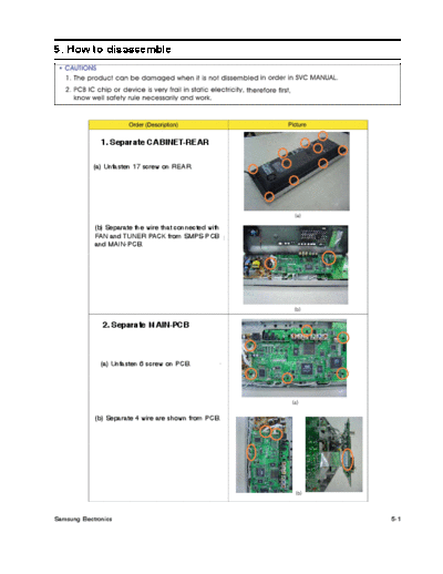
5. How to disassemble


               1. Separate CABINET-REAR

            (a) Unfasten 17 screw on REAR.


             (b) Separate the wire that connected with
             FAN and TUNER PACK from SMPS-PCB
             and MAIN-PCB.


               2. Separate MAIN-PCB


               (a) Unfasten 6 screw on PCB.


             (b) Separate 4 wire are shown from PCB.


Samsung Electronics                                      5-1
             3. Separate SMPS-PCB


          (a) Remove the SHIELD-HDMI.


          (b) Unfasten 4 screw
             and separate the SMPS-PCB.


            4. Separate FRONT-PCB


      (a) Unfasten 6 screw on FRONT-PCB.


      (b) Separate 1 wire are shown and
         then separate the FRONT-PCB.


5-2                                        Samsung Electronics
             5. Separate LED-PCB and LENS


            (a) Separate 2 hook staying fixed.


            (b) Unfasten 1 screw are shown and
               then separate the HOLDER-LENS.


               6. Separate DVD-MECHA


            (a) Unfasten 3 screw are shown and
               then separate the HOLDER-MECHA.


               7. Separate CABINET-FRONT


            (a) Unfasten 8 screw are shown and
               then separate the CABINET-FRONT.


             (b) Separate 2 wire are connected.


Samsung Electronics                               5-3
        8. Separate MOTOR


      (a) Unfasten 3 screw on HOLDER-GEAR-UP and
      3 screw on HOLDER-GEAR-DOWN.


         9. Separate SWITCH-LIFT PCB


      (a) Separate SWITCH-LIFT-UP and
       SWITCH-LIFT DOWN PCB are sticked on hook
        from COVER-FRONT.


5-4                                                Samsung Electronics
     * SUBW OOFER Disassemb l y


        1. Separate CABINET-REAR


          (a) Unfasten 12 screw on REAR.


        2. Separate AMP SET
             from SUBWOOFER


           (a) Separate SUB-WOOFER signal wire
              and FRONT LED3P wire.


Samsung Electronics                              5-5
        3. Separate MOLD CASE


      (a) Unfasten 6 screw are shown on REAR.


              (b) COMPLETE !


5-6                                             Samsung Electronics
◦ Jabse Service Manual Search 2026 ◦ Jabse Pravopis ◦ onTap.bg ◦ Other service manual resources online : Fixya ◦ eServiceinfo