Service Manuals, User Guides, Schematic Diagrams or docs for : Samsung GSM Samsung SGH-C520 service manual
<< Back | HomeMost service manuals and schematics are PDF files, so You will need Adobre Acrobat Reader to view : Acrobat Download Some of the files are DjVu format. Readers and resources available here : DjVu Resources
For the compressed files, most common are zip and rar. Please, extract files with Your favorite compression software ( WinZip, WinRAR ... ) before viewing. If a document has multiple parts, You should download all, before extracting.
Good luck. Repair on Your own risk. Make sure You know what You are doing.
Image preview - the first page of the document
>> Download Samsung SGH-C520 service manual documenatation <<
Text preview - extract from the document
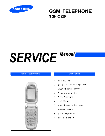
                GSM TELEPHONE
                SGH-C520


GSM TELEPHONE                      CONTENTS


                  1.   Specification

                  2.   Exploded View and Parts list

                  3.   Chart of Troubleshooting

                  4.   Array course control

                  5.   Block Diagrams

                  6.   PCB Diagrams

                  7.   MAIN Electrical Parts List

                  8.   Reference data

                  9.   Safety Precautions

                  10. Product Function
                                                         Contents


1. Specification
 1-1. GSM/CDMA General Specification ...........................................................................1-1
 1-2. GSM TX power class ...............................................................................................1-2


2. Exploded View and Parts list
 2-1. Cellular phone Exploded View ..................................................................................2-1
 2-2. Cellular phone Parts list ............................................................................................2-2
 2-3. Disassembly ...............................................................................................................2-4
 2-4. Assembly ....................................................................................................................2-8


3. Chart of Troubleshooting
     3-1. Baseband ............................................................................................................3-1
       3-1-1. Power ON .....................................................................................................3-1
       3-1-2. System Initial ................................................................................................3-6
       3-1-3. SIM Part .......................................................................................................3-8
       3-1-4. Charging Part .............................................................................................3-10
       3-1-5. Microphone Part .........................................................................................3-13
       3-1-6. Speaker Part ..............................................................................................3-16
       3-1-7. Receiver Part .............................................................................................3-20
       3-1-8. Camera Part ..............................................................................................3-22
              1) 2Mega Camera .....................................................................................3-22
              2) VGA Camera .........................................................................................3-23
       3-1-9. LCD .............................................................................................................3-26
     3-2. RF ......................................................................................................................3-13
       3-2-1. EGSM Receiver .........................................................................................3-30
       3-2-2. EGSM Transmitter .....................................................................................3-31
       3-2-3. DCS Receiver ............................................................................................3-32
       3-2-4. DCS Transmitter ........................................................................................3-33
       3-2-5. PCS Receiver .............................................................................................3-34
       3-2-6. PCS Transmitter .........................................................................................3-35
       3-2-7. UMTS Receiver ..........................................................................................3-40
       3-2-8. UMTS Transmitter ......................................................................................3-41
       3-2-9. BLUETOOTH ..............................................................................................3-45
                                                       Contents

4. Array course control
   4-1. Downloading Binary Files ......................................................................................4-2
   4-2. Pre-requsite for Downloading ................................................................................4-2
   4-3. S/W Downloader Program .....................................................................................4-3


5. Block Diagrams

6. PCB Diagrams

7. MAIN Electrical Parts List

8. Reference data
  8-1. Reference Abbreviate ..............................................................................................8-1


9. Safety Precautions
 9-1. Repair Precaution ......................................................................................................9-1
 9-2. ESD(Electrostaically Sensitive Devices) Precaution ................................................9-2


10. Product Function
1. Specification

1-1. GSM General Specification

                                G S M 9 00             EGSM 900           DCS1 800
                                Ph ase 1                Ph ase 2          Phase 1
   F r eq. Ban d[MHz]            89 0~9 15               88 0~9 15        171 0~ 178 5
    Up lin k/D own lin k         93 5~9 60               92 5~9 60        180 5~ 188 0

                                                        0~ 124 &
     ARF CN r a nge               1 ~12 4                                  51 2~ 885
                                                        975 ~1 023

     T x/ Rx s p ac in g         45 M H z                45 M H z          95 M H z


     Mod. Bit r ate/          270 .8 33 Kb ps         270 .8 33 Kb ps   270 .8 33 Kb ps
      Bit Period                3.692 us                3.692 us          3.692 us

T ime Slot Peri od/F r ame      576 .9 us                576 .9 us        576 .9 us
         Period                 4.615 ms                 4.615 ms         4.615 ms

       Mod ula ti on            0 .3 GMSK               0 .3 GMSK         0 .3 GMSK


       MS Power              33 dBm~ 1 3 dB m         33 dB m~ 5 dB m   30 dB m~ 0 dBm


      Powe r Cla ss            5 pcl ~ 15 pcl          5 pcl ~ 19 pcl    0 pcl ~ 15 pcl


       Sensi ti vity            - 10 2 dBm              -10 2 dBm         - 10 0 dBm


       TDMA Mux                      8                       8                 8


      C ell Rad ius               35 Km                   35 Km              2 Km


                                                1-1
Specification


1-2. GSM TX power class

     TX Power       GSM900      TX Power       DCS1800
    control level              control level

           5        33
◦ Jabse Service Manual Search 2026 ◦ Jabse Pravopis ◦ onTap.bg ◦ Other service manual resources online : Fixya ◦ eServiceinfo