Service Manuals, User Guides, Schematic Diagrams or docs for : Samsung DVD DVD-C350 Disassembly & Reassembly
<< Back | HomeMost service manuals and schematics are PDF files, so You will need Adobre Acrobat Reader to view : Acrobat Download Some of the files are DjVu format. Readers and resources available here : DjVu Resources
For the compressed files, most common are zip and rar. Please, extract files with Your favorite compression software ( WinZip, WinRAR ... ) before viewing. If a document has multiple parts, You should download all, before extracting.
Good luck. Repair on Your own risk. Make sure You know what You are doing.
Image preview - the first page of the document

>> Download Disassembly & Reassembly documenatation <<
Text preview - extract from the document
3. Disassembly and Reassembly
3-1 Cabinet and PCB

  CAUTION : Connector Must be remove with care

    SCREW SIZE INFORMATION


   (SCREW TYPE)               (SCREW SIZE)          (SCREW COLOR)
   M : MACHINE                  M1.7 x L9           B : Black
   T : TAPTYPE                                      W : White
                                                    S : Silver


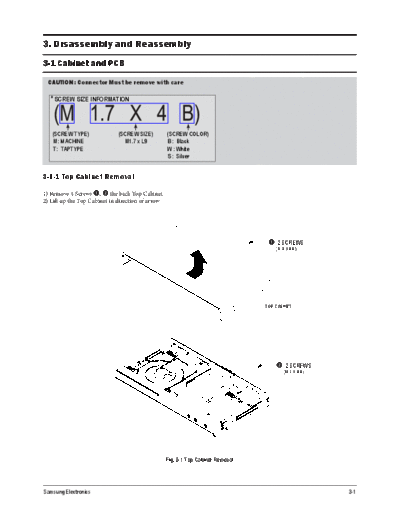
3-1-1 Top Cabinet Removal

1) Remove 4 Screws q, w the back Top Cabinet.
2) Lift up the Top Cabinet in direction of arrow.


                                                                                    q 2 SCREWS
                                                                                       (M 3 X 8 B)


                                                                                   TOP CABINET


                                                                                       w 2 SCREWS
                                                                                           (M 3 X 8 B)


                                                    Fig. 3-1 Top Cabinet Removal


Samsung Electronics                                                                                      3-1
Disassembly and Reassembly
3-1-2 Ass'y Front Cabinet Removal

1) Release 6 Hooks q, w, e, r and Ass'y Front-Cabinet t .


                q 1 HOOK


                                             w 2 HOOKS


                                                                   e 1 HOOK
                             r 2 HOOKS

                                             t ASSY FRONT CABINET


                                          Fig. 3-2 Ass'y Front Cabinet Removal


3-2                                                                              Samsung Electronics
                                                                                               Disassembly and Reassembly

3-1-3 Ass'y Loader Removal

1) Release Ass'y Loader FPC cable q from Ass'y Main PCB.
2) Remove 3 Screws w from the Ass'y Loader and lift it up.

               w 3 SCREWS
                 (M 3 X 6 W)


                                                                                ASS'Y LOADER


                                                                         q FPC CABLE
                                                                         ASS'Y LOADER - MAIN ASS'Y


                                                Fig. 3-3 Ass'y Loader Removal


Samsung Electronics                                                                                                  3-3
Disassembly and Reassembly
3-1-4 Main PCB and S.M.P.S PCB and Scart PCB Removal

1) Release FPC cable q from Ass'y Main PCB.
2) Remove 1 Screw w from the Scart PCB e and lift it up.
3) Remove 4 Screws w from the Main PCB and S.M.P.S PCB r, t and lift it up.

                                                                                    w 5 SCREWS
                                                                                       (M 3 X 6 W)


                                                                                   r MAIN PCB
                                                                                   q FPC CABLE - ASS'Y MAIN

                             t S.M.P.S PCB                                                      e SCART PCB


                                 Fig. 3-4 Main PCB and S.M.P.S PCB and Scart PCB Removal


3-4                                                                                                   Samsung Electronics
                                                                                        Disassembly and Reassembly

3-2 Pick-up disassembly and reassembly

3-2-1 Disassembly                                      3-2-2 Assembly

1) Remove the power cord.                              1) Replace the Pick-up.
2) Disassemble the Deck-Assy.                          2) Remove the soldering 2 points on Pick-up.
3) Make solder land 2 points short on Pick-up.         3) Reassemble the Deck-Assy.
   (See Fig. 3-5)
4) Disassemble the Pick-up.

  Note : If the assembly and disassembly are not done in correct sequence, the Pick-up may be damaged.


                                                   Fig. 3-5


Samsung Electronics                                                                                           3-5
Disassembly and Reassembly


                             MEMO


3-6                                 Samsung Electronics
◦ Jabse Service Manual Search 2024 ◦ Jabse Pravopis ◦ onTap.bg ◦ Other service manual resources online : Fixya ◦ eServiceinfo