Service Manuals, User Guides, Schematic Diagrams or docs for : Samsung DVD DVD-HR773 DVD HR775 HR773 HR776 HR777 CH3
<< Back | HomeMost service manuals and schematics are PDF files, so You will need Adobre Acrobat Reader to view : Acrobat Download Some of the files are DjVu format. Readers and resources available here : DjVu Resources
For the compressed files, most common are zip and rar. Please, extract files with Your favorite compression software ( WinZip, WinRAR ... ) before viewing. If a document has multiple parts, You should download all, before extracting.
Good luck. Repair on Your own risk. Make sure You know what You are doing.
Image preview - the first page of the document
>> Download CH3 documenatation <<
Text preview - extract from the document
3. Disassembly and Reassembly
3-1 Cabinet and PCB

 Note : Reassembly in reverse order.

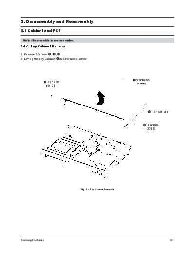
3-1-1 Top Cabinet Removal

1) Remove 5 Screws q, w, e.
2) Lift up the Top Cabinet r in direction of arrow.


                                                                            q 3 SCREWS
                  e 1 SCREW                                                   (3X10 B)
                      (3X10 B)


                                                                                         r TOP CABINET


                                                                                   w 1 SCREW
                                                                                         (3X8 B)


                                             Fig. 3-1 Top Cabinet Removal


Samsung Electronics                                                                                      3-1
Disassembly and Reassembly
3-1-2 Ass'y Front-Cabinet Removal

1) Release 7 Hooks q, w, e, r and Ass'y Front-Cabinet t.


               q 1 HOOK


                                            r 2 HOOKS


                                                                              w 1 HOOK

                                e 3 HOOKS
                                                           t ASS'Y FRONT-CABINET


                                       Fig. 3-2 Ass'y Front-Cabinet Removal


3-2                                                                                      Samsung Electronics
                                                                                              Disassembly and Reassembly
3-1-3 Hard Disk Removal

1) Remove 4 Screws q, w from the Ass'y Hard Disk e and lift it up.


                                                   q 2 SCREWS            w 2 SCREWS
                                                    (32UNC x M3)         (32UNC x M3)


                                                                                        e ASS'Y HARD DISK


                                            Fig. 3-3 Hard Disk Removal


Samsung Electronics                                                                                                 3-3
Disassembly and Reassembly
3-1-4 Ass'y Deck Removal

1) Remove 4 Screws q, w from the Ass'y Deck e and lift it up.


                                             w 2 SCREWS
                        q 2 SCREWS             (3X10 W)
                             (3X10 W)


                                                             e ASS'Y DECK


                                           Fig. 3-4 Ass'y Deck Removal


3-4                                                                         Samsung Electronics
                                                                                           Disassembly and Reassembly
3-1-5 Main PCB, S.M.P.S PCB and Front PCB Removal

1) Remove 7 Screws q, w, e from the Main PCB r and lift it up.
2) Remove 4 Screws t from the S.M.P.S PCB y and lift it up.
3) Remove 1 Screw u from the Front PCB i and lift it up.


                                 t 4 SCREWS
                                   (3X6 W)

                                                            q 4 SCREWS
                                                               (3X6 W)

                  y S.M.P.S PCB
                      u 1 SCREW
                       (3X6 W)


    i FRONT PCB                                                                              r MAIN PCB


                                                                                              w 3 SCREWS
                                                                                                 (3X10 B)

                                                                                                 e 1 SCREW
                                                                                                    (3X6 W)


                                    Fig. 3-5 Main PCB, S.M.P.S PCB and Front PCB Removal


Samsung Electronics                                                                                              3-5
Disassembly and Reassembly

3-2 PCB Location


              MAIN PCB
              S.M.P.S PCB


                                                     FRONT PCB


                             Fig. 3-6 PCB Location

3-6                                                              Samsung Electronics
◦ Jabse Service Manual Search 2026 ◦ Jabse Pravopis ◦ onTap.bg ◦ Other service manual resources online : Fixya ◦ eServiceinfo