Service Manuals, User Guides, Schematic Diagrams or docs for : Samsung Dishwashers DW80H9970US_AA Service Manual 5.TROUBLESHOOTING
<< Back | HomeMost service manuals and schematics are PDF files, so You will need Adobre Acrobat Reader to view : Acrobat Download Some of the files are DjVu format. Readers and resources available here : DjVu Resources
For the compressed files, most common are zip and rar. Please, extract files with Your favorite compression software ( WinZip, WinRAR ... ) before viewing. If a document has multiple parts, You should download all, before extracting.
Good luck. Repair on Your own risk. Make sure You know what You are doing.
Image preview - the first page of the document
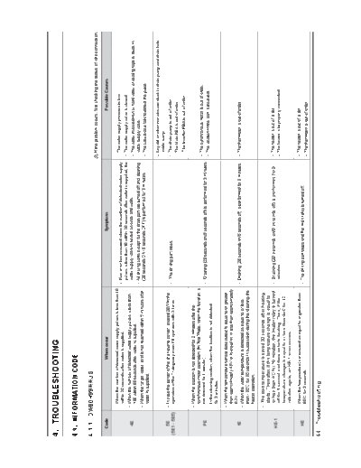
>> Download 5.TROUBLESHOOTING documenatation <<
Text preview - extract from the document
4. TROUBLESHOOTING
4-1. INFORMATION CODE
4-1-1. DW80H99 US
Code When occur Symptom Possible Causes
- When the number of detected water supply pulses is less than 10 - The water supply pressure is low.
within 20 seconds after water is supplied. - If an error has occurred when the number of detected water supply
pulses is less than 10 within 20 seconds after water is supplied, the - The water supply valve is closed.
- When the number of detected water supply pulses is less than water supply valve is turned on once and waits.
4E - The water involved iron or hard water or sealing tape is stuck in
100 within 80 seconds after water is supplied.
- All driving parts except for the drain part are turned off and draining water supply valve.
- When the target water level is not reached within 5 minutes after (20 seconds ON/ 5 seconds OFF) is performed for 3 minutes.
water is supplied. - The case brake fails to detect the pulse.
- Any dirt or other remains are stuck in drain pump and drain hole
inside sump.
5E - In case the power of the drain pump power exceed 20W in the - The drain pump is out of order.
- The driving part stops.
(5E1 - 5E5) operation of the Drain pump even if it operates with 3 times.
- The Main PBA is out of order.
- The Inverter PBA is out of order.
- When the location is not detected for 2 minutes after the
synchronous motor operation. (In Test Mode, when the location is
- The synchronous motor is out of order.
PE not detected for 1 minute.) - Draining (20 seconds on/5 seconds off) is performed for 3 minutes.
- The location in the cam is incorrect.
- In the cleaning section, when the location is not detected
for 3 minutes.
- When the temperature sensor data output is equal to or greater
than approximately 4.5V or is equal to or less than approximately
0.2V.
tE - Draining (20 seconds on/5 seconds off) is performed for 3 minutes. - The thermistor is out of order.
- When the water temperature is detected as equal to or less
than - 30 for 30 seconds in succession during the cleaning the
heater operation.
- The start temperature is saved 30 seconds after heating
starts. Thereafter, if the temperature change is equal to
or less than 4 for 10 minutes, the heater relay is turned - Draining (20 seconds on/5 seconds off) is performed for 3 - The heater is out of order.
HE-1
off for 1 second and then restarts heating. Then, if the minutes. - The heater is improperly connected.
temperature change is equal to or less than 4oC for 10
minutes again, an HE-1 error occurs.
- When the temperature is measured as equal to or greater than - The heater is out of order.
HE - The driving part stops and the main relay is turned off.
80 for 3 seconds. - The thermistor is out of order.
44 _ Troubleshooting
Code When occur Symptom Possible Causes
- When the button is pressed and held for 30 continuous seconds - The touch button is out of order.
bE2 - Normally working at washing mode
or longer. - An object is on the touch button.
- When IC communications between the Sub PBA and the - The touch button is out of order.
bE3 - Normally working at washing mode
touch button fails. - The sub PBA or touch button PBA is not properly connected.
- When communications between the main PBA and the - The main PBA or sub PBA is out of order.
AE sub PBA fails for 24 seconds. - Normally working at washing mode - The communications connection for the main PBA or sub PBA is
(In Test Mode, communication fails for 6 seconds.) not properly connected.
- When the response is not received from inverter PBA for - The main PBA or Inverter PBA is out of order.
AE6 3 seconds, Inverter RELAY OFF for 2 minutes. After - The driving part stops. - The communications connection for the main PBA or Inverter PBA
repeated 3 times, display the error code is not properly connected.
- If sensor data over 3V is detected after draining (20 seconds
on/5 seconds off) is performed for 3 minutes, the drain
- When the water leakage sensor data is equal to or less
LE pump is turned off. If data over 3V is detected, draining - There is a water leak.
than 3V for 3 seconds.
is performed for 3 minutes and then the sensed data is
checked again.
- If sensor data over 3V is detected after draining (20 seconds
on/5 seconds off) is performed for 3 minutes, the drain - The case brake fails to detect the pulse.
OE pump is turned off. If data over 3V is detected, draining - The valve water is out of order.
for 5 seconds.
is performed for 3 minutes and then the sensed data is - Any dirt or other remains are stuck in sump.
checked again.
- Power consumption of Circulation pump detected low
water level for 1 continuous seconds while a water
supply and wash is performed.
1) After the completion of the water supply.
- The motor is out of order.
If a low level is detected, additional water is supplied for
a predetermined period of time. If a low level is measured - Draining (20 seconds on/5 seconds off) is performed - If there are Bubbles in the tub.
1E
even after additional water is supplied, an 1E error for 3 minutes.
occurs.
- If there is excessive pollution in tub.
2) While a wash is performed. If a low level is detected,
additional water is supplied for a predetermined period
of time. If a low level is measured even after additional
water is supplied twice, an 1E error occurs.
Troubleshooting_45
Code When occur Symptom Possible Causes
Condition 1)
- When Main receives the Circulation pump error from
the inverter, stop the drive the motor and restart again.
If Main receive the motor error 11 times, turn off the
motor for 5 minutes. At the third rest time, Error occurs.
(When an error occurs, Heater is stopped immediately.
And Heater ON after operating the circulating motor
10 seconds.) - Any dirt or other remains are stuck in circulation pump and pump.
3E Condition 2) - The Circulation pump is out of order.
- 20 seconds ON/ 5 minute OFF. Drain for 3 minute.
(3E1 - 3E4) - Washing(Rinsing) area : When Target rpm is 2600rpm - The Main PBA is out of order.
or more and Circulation pump speed is 2400rpm or The Inverter PBA is out of order.
less continuously for three seconds, the operation is
stopped.
Retry 2 times in 3 seconds. When sensing 3 times,
Inverter is turned off and retry in 5 minutes.
At the third rest time, Error occurs.
(If the condition of Low level water sensing, this error is
ignored.)
- When the number of detected water supply pulses are
- Draining (20 seconds on/5 seconds off) is performed
200 at the Non-water supply mode.
4E5 for 3 minutes, and then 200pulse over again detected, - The water valve is out of order.
Repeats water valve on(1seconds) / off(1seconds)
repeat Draining.
2 times
If blackout or DC Link voltage is high or low voltage
9E1 - The driving part stops. - High or Low voltage is supplied.
conditions, switches to stop mode (abnormal voltage).
- Motor gear is out of order.
- Sensor vane is out of order.
Case1) When the reset position sensing for 10 seconds, - When the vane is blocked.
vane motor 1 sec Off and re-operation.
Error occurs after retry three times.
- Draining (20 seconds on/5 seconds off) is performed
7E Case2) When the reset position sensing for 25 seconds.
for 3 minutes.
Error occurs after retry three times.
Case3) Vane position is the time from initial position to initial
position in 21 seconds or less, the error occurs.
The vane is blocked something including forks and spoons.
46 _ Troubleshooting
4-2. SERVICE INSPECTION MODE
Press the 'Auto' + 'Delicate' + 'Power' buttons at the same time for two seconds to enter Service Inspection Mode.
You can change the mode by pressing the Normal button again. To advance to the next mode, press the normal button.
If you want to activate a mode while operating the dishwasher, the door must be closed.
If `LE' , `OE', `tE' error occur, enter Service Inspection Mode after resolving it.
Service Inspection Mode is described in the following table.
Item Related Parts Symptoms Description
Entering Test Mode
All Led Display n1 n2 n3 n4 n5 n6 n7 n8 n9 nA (Repeats) )
Changing the mode
"dE" error occurs.
Displaying all
Displaying the program
version
N1 (nA)
Turbidity Error
32)
A nozzle does not
n2 (nb)
inject water.
the "Middle up" runs for 1 minutes, change the order of operation.
Troubleshooting_47
Item Related Parts Symptoms Description
- Runs the circulation motor(BLDC: 2600 RPM, AC motor: Low).
A nozzle does not
n3 (nC) - If the normal water level is detected, "nC" is displayed. If the low water level is detected, "n3" is displayed.
inject water.
- The "lower all" runs for 1 minutes the "Middle up" runs for 1 minutes, change the order of operation..
- Circulation motor (BLDC : 3400 RPM, AC motor : LOW) runs.
- Heater is On after pump has been running for 10 seconds, when the normal water level is detected.
- If the low water level is detected, Heater off
n4(nd) Heater Error - If the heater runs for 3 minutes, the heater is automatically turned off.
- If the temperature is equal to or higher than 60 , the heater is turned off.
- When starting, the dispenser runs for 1 minute.
- The lower all runs for 3 minutes The middle up run for 3 minutes
- The circulation motor runs (BLDC: 2600 RPM).
- RPM display after operation circulation motor.
Distributor function
n5 - Each time press the Normal key, it is possible to change the rpm. (1200 ~ 3400rpm)
Error
- Each time press the Heavy key, it is possible to change position of distributer.
(1:Middle + Upper 2:Lower Right 3:Lower All 4:Lower Left)
Distributor function - The circulation motor runs (BLDC: 3400 RPM, AC motor: High).
n6
Error - The synchronous motor runs by alternating the location between lower right and lower left at 1 minute intervals.
- Runs the vent motor and the thermal actuator of the dryer unit.
The Dry Fan motor - Turbidity sensor detect turbidity data.
n7
does not work. - Turbidity data displayed.
- If reference voltage can not be reached after sensing, occurs E3 error
n8 Over level water Error
- Runs the drain pump for 60 seconds (25 seconds on / 2 seconds off).
n9 Drain Error - If drain is not complete(Measuring power consumption drainage), occurs 5E error
- When drain is complete, display nP
48 _ Troubleshooting
Item Related Parts Symptoms Description
1. Lower Key : Lower Led On
Dry Fan(Auto LED) Dry Actuator(Normal LED) Dispenser Actuator(Heavy LED) Off
2. Booster left Key : Booster left LED On
Drain pump (Auto LED) Circulation Motor(low) / BLDC motor (Normal LED) Circulation Motor(low) /
nA BLDC motor (Heavy LED) Off
Circulation Pump Runs Max. 3 seconds to prevent damage c-pump.
3. Booster Right Key : Booster Right LED On
Distributer motor(Auto LED) Valve water (Normal LED) Heater(Max.operating 2seconds) (Heavy LED)
Vane CW (Delicate LED) Vane CCW (Express LED) Off
Troubleshooting_49
Error Type Error mode Checking method Corrective actions
1. Check whether the faucet is open. - Open the faucet.
- After wait until the water supply resumes and turn off the power.
2. Check whether the water supply has been cut off.
After the water supply resumes, turn on the power.
3. Check whether any foreign material is in the Water Supply
4. Check the connection for the Water Valve connector. - Reconnect the Water Valve connector.
5. Check whether the coil in Water Valve is conductive.
(Remove the connector before measuring.) - Faulty: Replace the Water Valve.
Water supply 4E
error 4E-1 6. Check whether the water supply stops, after water is
- Faulty: Replace the Water Valve and Flow Meter.
supplied for 20 seconds.
7. Check whether the water supply stops after water is - Check the water supply pressure. (> 0.5bar)
supplied for 80seconds or 5 minutes. - Faulty: Replace the Water Valve and Flow Meter.
8. Check whether the Water Valve is operating normally in the
Main PBA.
- Check the Water Valve Relay in Main PBA. : Check the - Faulty: Replace the Main PBA assy.
voltage between the Black wire (Number 9) of the CN202 - Normal: Replace the Water Valve
and the Black wire of the CN101 connector.
Normal: 110 ~120V (while operating)
9. Check the Power Relay. - See the "Power Relay error".
50 _ Troubleshooting
Error Type Error mode Checking method Corrective actions
1. Check whether there is any foreign material in the Drain - Remove the foreign material in the Drain Hose, Drain Pump, drain hole inside
Hose, Drain Pump, drain hole inside sump. sump.
2. Check the connections for the Drain Pump connector. - Reconnect the Drain Pump connector.
3. Check whether the Drain Pump coil is conductive.
(Remove the connector before measuring.) - Faulty: Replace the Drain Pump.
4. Check the operation of the Inverter PBA
4-1. Check the operating AC voltage of the Inverter PBA
CN5 connector. - Faulty: Replace the Main PBA assy
Normal: 110V ~ 120V (while operating)
5E
Drain error
(5E1 - 5E5)
4-2. Check the operating LED(red) of the inverter PBA.
- Faulty: Replace the Inverter PBA assy.
Normal: Fully turn-on (while operating)
4-3. Check the operating voltage between #1 and #2 of
the Inverter PBA CN8 connector at LA in test mode.
- Faulty: Replace the Inverter PBA assy.
Normal:50V ~ 90V (while operating) - Normal: Check a connection between the Inverter PBA and the Drain Pump.
How to do LA in test mode
- Push Booster left key+Booster right key+Power key at
the same time.
- Push the Linear Auto key
Check whether there is condensation on the PBA.
- Faulty : Remove any condensation and moisture.
Key input bE-2 - CN103 of Display Control Module connector
- Normal : Replace the Control Panel assy.
error bE-3 - CON100 TOUCH Module connector
(Display Control Module, Touch Module, Sub Wire)
Normal: No condensation
Troubleshooting_51
Error Type Error mode Checking method Corrective actions
1. Check whether there is any foreign material in the
- Remove the foreign material in the Circulation Hose and Circulation Pump.
Circulation Hose and Circulation Pump.
2. Check the connections for the Circulation Pump connector. - Reconnect the Circulation Pump connector.
3. Check whether the Circulation Pump coil is conductive.
(Remove the connector before measuring.) - Faulty: Replace the Circulation Pump.
4. Check the operation of the Inverter PBA
4-1. Check the operating AC voltage of the Inverter PBA CN5
connector - Faulty: Replace the Main PBA assy
Normal : 110V ~ 120V (while operating)
Circulation 3E
Pump error (3E1 -3E4)
4-2. Check the operating LED(red) of the inverter PBA
- Faulty: Replace the Inverter PBA assy.
Normal : Fully turn-on (while operating)
4-3. Check the operating voltage between #1 and #2 of the
Inverter PBA CN6 connector at L3(Lc) in test mode
Normal : 50V ~ 90V (while operating) - Faulty: Replace the Inverter PBA assy.
How to do L3(Lc) in test mode - Normal: Check a connection between the Inverter PBA and the Circulation
- Push Booster left key+Booster right key+Power key at the Pump.
same time
- Push the Linear Auto key
52 _ Troubleshooting
Error Type Error mode Checking method Corrective actions
1. Check the connections of the Heater connectors. - Reconnect the Heater connectors.
2. Check the resistance between both ends of the Heater.
: Check the resistance between both ends of the Heater
directly, or check the resistance between the red wire of the
Heater Relay and the black and yellow wires of the Power - Faulty: Replace the Heater.
Relay, respectively.
Heater 3. Check the connections of the Heater Relay in Main PBA.
HE-1 : Check the voltage between the Red wire of the Heater
error
Relay on the base and the Black wire of the CN101 - Reconnect the Heater Relay connectors.
connector.
Normal : 110 ~ 120V (while operating)
4. Check the driving signals for the Heater Relay.
Measure the voltage between pin 1(D12 Anode side) of the
Main PBA
RY201 relay and pin 2 of the CN402 connector. - Faulty: Replace the Main PBA assy.
When the Heater is off : 10.5 to 13V
When the Heater is operating : < 0.5V
5. Check the Power Relay. - See the "Power Relay error".
Heater Overheat 1. Check the operation of the Thermistor. - See the "tE Error".
HE
error 2. Check the Heater Relay. - See the "HE-1 Error".
Check whether there is any trace of water leakage in the
Leakage shutter. - Faulty: Check the leakage location.
LE
error - Replace the faulty part.
Normal: No water leakage trace
Troubleshooting_53
Error Type Error mode Checking method Corrective actions
- Reconnect the Distributor Motor and Micro Switch connectors.
1. Check the connections for the Distributor Motor and Micro
Switch connectors.
2. Check whether the coil in Distributor Motor is conductive.
: Remove the connectors before measuring. - Faulty: Replace the Distributor Motor.
3. Check the position sensing operations when turning the
Micro Switch on and off.(Use n5 Service test mode.) - Faulty: Replace the Micro Switch for sensing positions.
Check the conduction between the brown wire and the - Normal: Replace the valve distributor and CAM switch.
Violet wire.
Micro switch On: Short
Half load error PE
Micro switch Off: Open
- Micro Switch sign alters in ON/OFF state.
- It is NG if keep in ON or OFF state for 120 seconds.
* Do not supply with water and test.
4. Adjust Cam A'ssy and Find the faulty. - Faulty: Replace Cam A'ssy.
5. Check whether half load is operating normally. - Faulty: Replace the Main PBA assy.
- Check the half load operation
Normal : 110 ~ 120V
- Check the operation of Distributor Motor Relay.
: Check the operating voltage between the 3pin(Brown) wire
of the Main PBA CN201 connector and the 1pin(Black)
wire of the Main PBA CN101 connector
Normal : 110 ~ 120V (while operating)
6. Check the Power Relay. - See the "Power Relay error".
54 _ Troubleshooting
Error Type Error mode Checking method Corrective actions
1. Check the connections for the Motor vane and Sensor
- Reconnect the Distributor Motor and Micro Switch connectors.
vane connectors.
2. Check whether the coil in Motor vane is conductive.
Check the resistance between the Red and Black wire(CCW)
Check the resistance between the White and Black wire(CW). - Faulty: Replace the Motor vane.
: Remove the connectors before measuring.
- Faulty: Replace the Sensor vane for sensing positions.
- Normal: Replace the Motor vane and Sensor vane
3. Check the position sensing operations when moving the
Sensor vane on and off.(Use n5 Service test mode.)
Check the conduction between the Brown wire and the
Black wire.
Motor vane Sensor On: 0V
7E Sensor Off: 5V
error
4. Adjust Motion A'ssy and Find the faulty. - Faulty: Replace Motion A'ssy.
5. Check whether Motor vane is operating normally.
- Check the Motor vane operation - Faulty: Replace the Main PBA assy.
Normal: 110 ~ 120V
- Check the operation of Motor vane Relay.
- CCW: Check the operating voltage between the 5pin(Red)
wire of the Main PBA CN202 connector and the
Black wire of the Main PBA CN101 connector
CW: Check the operating voltage between the
5pin(White) wire of the Main PBA CN202 connector
and the Black wire of the Main PBA CN101
connector
Normal: 110 ~ 120V (while operating)
6. Check the Power Relay. - See the "Power Relay error".
Troubleshooting_55
Error Type Error mode Checking method Corrective actions
2. Check whether the Water Valve operates normally. Use
- See "4E Error".
d07 Display mode.
OE
error 3. Check whether water is supplied (even small amounts) in - Remove foreign material from the Water Valve.
the intervals when the Water Valve is not operating. - If you cannot remove the foreign material from the Water Valve, replace it.
- Assy Case Brake replace.
1. Check the connections for the Thermistor connector - Reconnect the Thermistor connector.
2. Check whether the Thermistor is operating normally.
- Measure the voltage between both ends of the
Thermistor.
Normal: 0.05 to 4.95V
- Measure the resistance between both ends of the
Thermistor
: Remove the connector before measuring.
(See the Table right.)
- Faulty: Replace the Thermistor.
Thermistor table - Normal: Replace the Main PBA assy
Temp( )
Thermistor 5 125.814
tE
Error 10 98.360
15 77.480
20 61.477
25 49.120
30 39.510
35 31.985
40 26.053
45 21.347
50 17.590
55 14.573
60 12.136
65 10.157
70 8.541
56 _ Troubleshooting
Error Type Error mode Checking method Corrective actions
1. Check the connections between MAIN PBA CN402
- Reconnect the MAIN PBA CN402 connector and SUB PBA CN101 connector
connector and Display Control Module CN101 connector
2. That Error is produced continuously after method 1
Main-Sub PBA - Replace: Sub-Wire
Communication AE
error 3. That Error is produced continuously after method 2
- Replace: Sub-PBA
4. That Error is produced continuously after method 2
- Replace: Main-PBA
1. Check the connections for the Pump BLDC connectors. - Reconnect the Pump BLDC connectors
Motor BLDC
1E 3. Do it to act Test service test mode L2, L3 and motor(water)
error - Faulty: Replace motor
4. Problem occurrence to Method 1,2,3. - Faulty : Replace Main-PBA.
- Reconnect the Main PBA CN401 connector and
Inverter PBA CN1 connector
1. Check the connections between Main PBA CN401 CN1
BLDC connector and Inverter PBA CN1 connector CN401
Motor
AE6
Communication
error
2. That Error is produced continuously after method 1
- Replace: Inverter PBA
3. That Error is produced continuously after method 2
- Replace: Main PBA
Troubleshooting_57
Error Type Error mode Checking method Corrective actions
1. Check the connections for the power plug. - Reconnect the power plug.
2. Check the voltage of the power outlet.
- Connect to a 120V power source.
Normal : 120V
3. Check Power Key on state. - Try to touch the Power key.
4. Check the connections for the Sub PBA and Touch PBA
- Reconnect the Sub PBA and Touch PBA connectors.
connector parts.
5. Check the connection of the Main PBA connector CN101 - Reconnect CN101
6. Check the connections for the Sub PBA and Main PBA
- Reconnect the Sub PBA and Main PBA connectors.
connector parts and
7. Check whether there is condensation on the PBA.
No Power error None - CN103 of Display Control Module connector - Faulty: Remove any condensation and moisture.
- CON100 TOUCH Module connector - Normal: Replace the Control Panel assy.
Normal: No condensation
8. Check whether the fuse is broken. - Replace the fuse (15A).
9. Check the DC voltage of the Main PBA. - See "Main PBA DC voltage error".
10. Check the wires of the Main PBA power part.
- Measure the voltage between the pin 1 wire and
the pin 3 wire of CN101. - Faulty: Check and replace the wires of the power part.
Nomral: AC 120V
11. In case of is No Power after Method 1~10 action - Replace the Control Panel assy. (Sub, Touch, wire)
12. In case of is No Power after Method 1~11 action - Replace the Main PBA.
58 _ Troubleshooting
Error Type Error mode Checking method Corrective actions
1. Check the connections for the Display LED connector part. - Reconnect the connectors for Display LED.
Display error None
2. Check the Display LED. - Faulty: Replace the Display LED and Sub PBA.
1. Check the wire connections for the Fan Motor. - Reconnect the Fan Motor connectors.
- Faulty: Replace the Fan Motor assy.
2. Check the resistance of the Fan Motor coil.
(Remove the connector before measuring.)
Dry error None
- Faulty: Replace the Main PBA assy.
3. Check the operation of the Fan Motor Relay
: Check the operating voltage between the red wire of the
CN201 connector and the Black wire of the CN101
connector.
Normal: 110V ~ 120V (while operating)
4. After Method 1~3, if dry performance is bad. - Faulty : Replace the Dry duct replace.
Troubleshooting_59
Error Type Error mode Checking method Corrective actions
1. Check whether detergent is inserted into the dispenser. - Check whether there is detergent in the Dispenser.
2. Check the connections for the Dispenser connector. - Reconnect the Dispenser connector.
- Faulty: Replace the Dispenser.
3. Check the resistance of the Dispenser.(Remove the
connector before measuring.)
Detergent
is not None - Faulty: Replace the Main PBA assy.
dispensed
4. Check the operation of the Dispenser Relay
: Check the operating voltage between the Black wire of
the CN201 connector and the Black wire of the CN101
connector.
Normal: 110V ~ 120V (while operating)
No washing None 2. Check Rotors and ducts and vane - Faulty: Replace Rotors and ducts.
3. Check the operation of the half load. - See "PE Error".
60 _ Troubleshooting
◦ Jabse Service Manual Search 2026 ◦ Jabse Pravopis ◦ onTap.bg ◦ Other service manual resources online : Fixya ◦ eServiceinfo