Service Manuals, User Guides, Schematic Diagrams or docs for : Samsung Dryer DV42H5000GW_A3 Disassembly_and_Reassembly-2
<< Back | HomeMost service manuals and schematics are PDF files, so You will need Adobre Acrobat Reader to view : Acrobat Download Some of the files are DjVu format. Readers and resources available here : DjVu Resources
For the compressed files, most common are zip and rar. Please, extract files with Your favorite compression software ( WinZip, WinRAR ... ) before viewing. If a document has multiple parts, You should download all, before extracting.
Good luck. Repair on Your own risk. Make sure You know what You are doing.
Image preview - the first page of the document
>> Download Disassembly_and_Reassembly-2 documenatation <<
Text preview - extract from the document
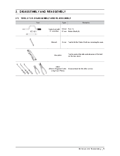
3. DISASSEMBLY AND REASSEMBLY
3-1. TOOLS fOR DISASSEMBLY AND REASSEMBLY
Tool Type Remarks
Socketsetwith 14 mm Fan(1)
6"extention 17 mm RollerShaft(4)
17 mm
14 mm
Wrench 8 mm TooltofixtheRollerShaftonremovingthenuts.
Tooltoprotecttheidleandabrasionofthebolt
Vicepliers
fortheboxdriver.
Other
(Driver,DiagonalCutter, Generaltoolsfortheafterservice.
LongNosePliers)
Removal and Reassembly _ 9
3-2. STANDARD DISASSEMBLY DRAWINGS
To avoid risk of electrical shock, personal injury or death, disconnect the power to the Clothes Dryer.
Thisisastandarddisassemblydiagramandmaydifferfromtheactualproduct.
Usethismaterialasareferencewhendisassemblingandreassemblingtheproduct.
Part figure Description
1. Disconnectthepowersupplyandtotheunit
2. Remove2screwsfromtheTop-Cover
Top Cover Removal
3. SlideTopCovertowardstherearandliftfromthe
unit.
Scratchandimpacttothetopcoveris
prohibited.
10 _ Removal and Reassembly
Part figure Description
1. Disconnectthepowersupplytotheunit.
2. RemovetheTop-Cover.
3. Remove2screwsfromtheGuide-Panel.
4. Separate6HookfromGuidePanel.
5. RemoveConsole.
Console Removal
6. RemoveEachHousing.
8. RemovescrewsfromtheAssyPCBSub.
Becarefulofexternalscratchontheconsole.
Removal and Reassembly _ 11
Part figure Description
1. Disconnectthepowersupplyandtotheunit
2. RemovetheTopCover
3. Remove3screwsfromtheframe+plate
4. RemovetheWireholder
Main PCB Removal
5. RemovetheHousings
Shakingtheheaterterminalsidewaystopullit
outisprohibited.
12 _ Removal and Reassembly
Part figure Description
1. Door Opening
2. Remove2screwsfromtheFramepanel
3. Separatethetemporaryfixationpartofthe
AssemblyDoor.
4. Remove14screwsfromtheHolderGlass
5. RemovetheDoor-Cover
Door Removal
6. Remove4crewsfromtheSupport-Hinge
7. RemovetheSupport-Hinge,Hinge
8. RemovetheDoorSeal
A. BecarefulnottoscratchtheDoor-Cover.
B. BecarefulofthedamagetotheDoorGlass.
C. ChecktheDoorSealconditionafterthe
assembly.
Removal and Reassembly _ 13
Part figure Description
1. DisconnectthePowerSupplytotheunit
2. RemovetheTopCover,andtheConsole
3. Removethefilter
4. Remove2screwsfromtheFrameFront
frame Panel 5. Remove4screwsfromthePlate(u)
Removal
6. RemovetheDoorSwitchHousing
WhenreassembleDoorSwitchtoFramePanel,
becarefulforinsertdirection.
7. LifttheFrontPaneloffthethreetabsacrossthe
bottomandremove
1. DisconnectthePowerSupplytotheunit
2. RemovetheTopCover,theConsole,andtheFront
Plate Removal
Panel
3. Remove4screwsfromthePlate(u)
14 _ Removal and Reassembly
Part figure Description
1. Disconnectthepowersupplytotheunit
2. RemovetheTopCover,theConsole,thefront
panelandthePlate(u)
3. SeparatethewireinthewireHolder(2EA)
4. DisconnectInteriorLightwiringHarness
5. Removethefourbulkheadretaining5screws.
6. DisconnecttheMoistureSensorwiringHarness
front Bulkhead
Removal
(Continued)
7. LiftBulkheadfromtheCabinetthenremoveit.
8. Remove2screwsfromtheDuctOutlet
9. RemovetheDuctOutlet
Removal and Reassembly _ 15
Part figure Description
10.RemoveClipandRoller.
11.Remove2screwsfromtheCaseFilter(B).
12.Remove1screwfromtheCaseFilter(F).
front Bulkhead
Removal
13.RemovetheCaseFilter(B/F).
MakesuretheFilterdoesnotgetdamagedby
theRoller.
14.Disconnect2HousingSensor-Plate.
15.Remove2Sensor-Plate.
16 _ Removal and Reassembly
Part figure Description
1. DisconnectthePowerSsupplytotheunit
2. RemovetheTopCover,theConsole,theFront
Panel,thePlate(u),andtheFrontBulkhead
3. RemoveBelt
Drum Removal
4. RemovetheDrum
Whenreassemblethebelt,makeitlocated
between2redarrows.
1. Disconnectthepowersupplytotheunit
2. RemovetheTopCover,theConsole,andtheFront
Panel
3. Remove2HousingSensor
Sensor
(Thermistor,
Thermostat)
Removal
4. RemovetheSensor
Donotapplyexcessiveforcetotheterminal.
RemovalandReassembly_17
Part figure Description
1. Disconnectthepowersupplytotheunit
2. RemovetheTopCover,theConsole,andtheFront
Panel
3. Removal6HousingHeater-Terminals
4. Remove1screwfromtheHeater
Heater Removal
5. SeparatetheHeaterfromtheDrum-back
6. Remove4screwsfromtheThermostats
Donotapplyexcessiveforcetotheterminal.
18 _ Removal and Reassembly
Part figure Description
1. Disconnectthepowersupplytotheunit
2. RemovetheTopCover,theConsole,theFront
Panel,thePlate(u),theFrontBulkheadandthe
Drum
3. Remove2screwsfromtheDuctConnector
4. SeparatetheDuctConnector
Assy Motor Removal
(Continued) 5. Remove1HousingMotor.
6. Remove2HousingBeltCutOffSwitch.
7. Remove3screwsfromtheMotor-Bracket.
Removal and Reassembly _ 19
Part figure Description
8. SeparatetheMotorAssyattheBottomPlate
9. Remove 1 Nut Fan
10.RemovetheFan
Assy Motor Removal
(Continued)
11.Remove3screwsfromtheCover-DuctFan
12.Removethe2SpringPlate
13.Removethe1screwBeltcutOffSwitch
20 _ Removal and Reassembly
Part figure Description
14.RemovetheHolderShaft
Assy Motor Removal
15.RemovetheRoller-Idler
Removal and Reassembly _ 21
Part figure Description
1. DisconnectthePowerSupplytotheunit.
2. RemovetheTopCover,theConsole,theFront
panel,thePlate(u),theFrontBulkheadandthe
Drum.
3. Remove8screwsfromtheDrum-Back.
4. Remove2screwsfromtheValve-Water.
5. SeparatethewireintheWireHolder.
Drum Back Removal
(Continued)
6. SeparatetheDrumBackfromtheFrame.
7. RemovetheterminalsfromtheValve-Water.
22 _ Removal and Reassembly
Part figure Description
8.Remove4screwsfromtheAirDuct.
Becarefuloftheframeedge.
Drum Back Removal 9. Removethe2screwsfromtheGuideNozzle.
10.Removethe1screwfrontheAssyThermistor.
1. Disconnectthepowersupplytotheunit.
2. Remove1screwfromtheBack-Cover.
Duct Exhaust
Removal
3. Remove1screwfromtheDuct-Exhaust.
Incasethescrewsforfixingapowercode
aredroppedintothedryer,afterremovingDuct
Exhaust,youcanputitoutthroughthehole.
Removal and Reassembly _ 23
Part figure Description
1. Unplugthepowercord.
2. Remove2doorhingescrews.
3. Liftthedoorandremoveit.
4. Remove2screwsfromtheFrameFront.
5. Removethe2screwsfromtheoppositesideofthe
DoorHinge.
DOOR REVERSAL
(Continued)
6. Remove2screwsfromtheHolderLever.
7. Reassemble2screwsonInsideHoles.
8. Remove1blackscrewfromtheDoorHinge.
Theblackscrewisforpre-fixingtheDoortothe
Frame Front.
24 _ Removal and Reassembly
Part figure Description
9. Reassembletheblackscrewintheotherhole.
10.Placethedoorontheothersideandreattachitto
thedryer.
DOOR REVERSAL
11.ReattachtheHolderLever.
12.ReattachthescrewsintheRemainingHoles.
Reassemblyproceduresareinthereverseorderofdissasemblyprocedures.
Removal and Reassembly _ 25
◦ Jabse Service Manual Search 2026 ◦ Jabse Pravopis ◦ onTap.bg ◦ Other service manual resources online : Fixya ◦ eServiceinfo