Service Manuals, User Guides, Schematic Diagrams or docs for : Samsung Dryer DV42H5000GW_A3 PCB_DIAGRAM-2

<< Back | Home

Most service manuals and schematics are PDF files, so You will need Adobre Acrobat Reader to view : Acrobat Download Some of the files are DjVu format. Readers and resources available here : DjVu Resources
For the compressed files, most common are zip and rar. Please, extract files with Your favorite compression software ( WinZip, WinRAR ... ) before viewing. If a document has multiple parts, You should download all, before extracting.
Good luck. Repair on Your own risk. Make sure You know what You are doing.


Image preview - the first page of the document
PCB_DIAGRAM-2


>> Download PCB_DIAGRAM-2 documenatation <<

Text preview - extract from the document
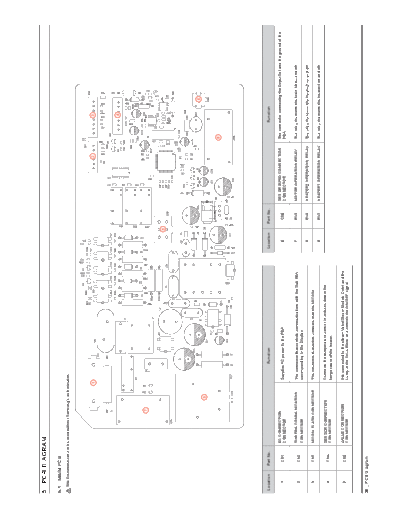
5. PCB DIAGRAM

5-1. MAIN PCB
  ThisDocumentcannotbeusedwithoutSamsung'sauthorization.


                                                   1                                                                                                    2                 3


                                                                                                                                                                          4


                                     7


                                                                                                                        5


                                                                                                                                                                                  6
                                            9


                                                                                                                                                               8


 Location   Part No.                                           function                                      Location       Part No.                                   function

                       AC CONNECTION                                                                                                   SETGROUNDCONNECTION     TheconnectorconnectingtheDryerSetandthegroundofthe
    1        CN1                                       SuppliesACpowertothePBA                                  6            CN6
                       CONNECTOR                                                                                                       CONNECTOR               PBA

                       SUB PBA COMMUNICATION           TheconnectorthatcontrolscommunicationswiththeSubPBA      7            RY5       MOTOR OPERATION RELAY   TherelaythatturnstheMainMotorandoff.
    2        CN2
                       CONNECTOR                       correspondingtotheDisplay.
                                                                                                                8            RY6       HEATER2OPERATIONRELAY   TherelaythatturnstheHeater2onandoff.
    3        CN3       MICOMFLASHCONNECTOR             TheconnectorthatwritessoftwareontotheMICOM.
                                                                                                                9            RY7       HEATER1OPERATIONRELAY   TherelaythatturnstheHeater1onandoff.
                       SENSOR CONNECTION               Connectsthetemperaturesensorinordertodetectthe
    4        CN4
                       CONNECTOR                       temperatureoftheheater.

                       VALVECONNECTION                 ItisconnectedtothesteamValve(SteamModelsOnly)andthe
    5        CN5
                       CONNECTOR                       LampoftheDriveBlockandcontrolstheON/OFFsignal.


38 _ PCB Diagram
5-2. DETAILED DESCRIPTIONS Of CONTACT TERMINALS (MAIN PCB)
  ThisDocumentcannotbeusedwithoutSamsung'sauthorization.


                                                                                                                                     CN3
                                                                                                                               1.    5V
                                                                             CN5                    CN2                        2.    SO
                                                                        1.   STEAMVALVE1       1.   CommunicationsPort(Rx)     3.    SI
                                                                        2.   Empty Pin         2.   CommunicationsPort(Tx)     4.    RESET
                            CN1                                         3.   LAMP              3.   SUB RESET                  5.    CLOCK
                       1.   ACPowerPort                                 4.   Empty Pin         4.   5V                         6.    FLMDO
                       2.   ACPoweroffDetectionSensor                   5.   STEAMVALVE2       5.   DGND                       7.    DGND
                       3.   DoorDetectionSensor(LOCK,UNLOCK)            6.   Empty Pin         6.   12V                        8.    Empty Pin


                                                                                                                                                      CN4
                                                                                                                                                 1.   DGND
                                                                1 g 3                                               6 g 1    8 g 1
                                                                                                                                                 2.   5V
                                                                                                                                                 3.   TEMP Sensor1
                                                                                                                             7 g 1
                                                                                                                                                 4.   FabricDetectionSensor
                                                                                                                                                 5.   FabricDetectionSensor
               RY5                                                                                                                               6.   5V
              1. MotorRelaySwitch                                                                                                                7.   TEMP Sensor2
                                                                                           3 g 1
              2. MotorRelaySwitch
                                                                                           4 g 6


                                                                                                                                                  CN6
                                                                                                                                                 1. SETGND


                                                 RY7                                                                 RY6
                                                1. Heater1RelaySwitch                                               1. Heater2RelaySwitch
                                                2. Heater1RelaySwitch                                               2. Heater2RelaySwitch


                                                                                                                                                                    PCB Diagram _ 39
5-3. SuB PCB
  ThisDocumentcannotbeusedwithoutSamsung'sauthorization.


                                                                                                                                                                   2
                                                                                                                                                               3


                                                                                          1
                                                                                                                                                   4


                          Location               Part No.                      function                                            Description

                             1                     BZ2      BuzzerCircuit                     BegeneratedsoundwhenKeyispressedortheencoderisoperated.

                             2                   CN202      Connect Main PBA                  ReceivespowerfromtheMainPBAandprovidesacommunicationsfunction.

                             3                   CN701      DrumLightCircuit                  ItcontrolsdrumlightLEDOn/Off

                             4                   CN402      ConnectTouchSensor                Supplyspowertotouchsensorandprovidesacommunicationsfunction.


40 _ PCB Diagram
5-4. DETAILED DESCRIPTIONS Of CONTACT TERMINALS (SuB PCB)
  ThisDocumentcannotbeusedwithoutSamsung'sauthorization.
                                                                                               CN202
                                                                                              1. CommunicationsPort(Tx)
                                                                                              2. CommunicationsPort(Rx)
                                                             CN701                            3. ResetSignalinput
                                                            1. 12V                            4. 5V
                                                            2. Unused pin                     5. GND
                                                            3. Drumlightcontrolpin            6. 12V


                                                                                                  6    1


                                                                                          3   1


                                                                                 5    1


                                                                      CN402
                                                                     1. 12V
                                                                     2. GND
                                                                     3. TouchcommunicationPort(SDA)
                                                                     4. TouchcommunicationPort(SCL)
                                                                     5. Unused pin


                                                                                                                          PCB Diagram _ 41


◦ Jabse Service Manual Search 2024 ◦ Jabse PravopisonTap.bg ◦ Other service manual resources online : FixyaeServiceinfo