Service Manuals, User Guides, Schematic Diagrams or docs for : Samsung LCD TV N99A chassis SAMSUNG_UN46C9000ZFXZA_UN55C9000ZFXZA_Chassis_N99A Disassembly & Reassembly
<< Back | HomeMost service manuals and schematics are PDF files, so You will need Adobre Acrobat Reader to view : Acrobat Download Some of the files are DjVu format. Readers and resources available here : DjVu Resources
For the compressed files, most common are zip and rar. Please, extract files with Your favorite compression software ( WinZip, WinRAR ... ) before viewing. If a document has multiple parts, You should download all, before extracting.
Good luck. Repair on Your own risk. Make sure You know what You are doing.
Image preview - the first page of the document
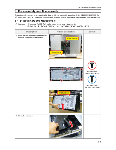
>> Download Disassembly & Reassembly documenatation <<
Text preview - extract from the document
3. Disassembly and Reassemble
3. Disassembly and Reassembly
This section of the service manual describes the disassembly and reassembly procedures for the UN46/55C9000ZF LED TV.
WARNING: This LED TV contains electrostatically sensitive devices. Use caution when handling these components.
3-1. Disassembly and Reassembly
Cautions: 1. Disconnect the LED TV from the power source before disassembly.
2. Follow these directions carefully; never use metal instruments to pry apart the cabinet.
Description Picture Description Screws
1. Place the face down on cushioned table.
Remove screw from stand bottorm.
Rear cover
Stand box
6003-000133
(M4, L8, MACHINE)
6003-001003
(M4, L12, TAPTYPE)
Stand box
2. Lift up the rear-cover.
3-1
3. Disassembly and Reassemble
Description Picture Description Screws
3. Remove screw from rear cover.
6003-000133
(M4, L8, MACHINE)
Lift up the Stand.
in case of wall-mount
1. Remove the TV from Wall.
2. Remove the Screws from Stand Box.
6003-000133
(M4, L8, MACHINE)
3. Remove the Stand box from Panel.
3-2
3. Disassembly and Reassemble
Description Picture Description Screws
4. Remove screw from stand box,
lift up the stand box cover.
6003-001003
(M4, L12, TAPTYPE)
5. Remove the Main board.
Lift up the Woofer.
Remove the cable from Main_docking
board.
Remove the screw of the Main_docking
board and lift up LVDS connector locking
of main board.
6001-002283
(M3, L5, Machine)
3-3
3. Disassembly and Reassemble
Description Picture Description Screws
Remove the Main_docking board.
Remove the screw of main board.
6001-002283
(M3, L5, Machine)
Remove the main board.
* when remove the main board,
sliding to the left and lift up
6. Remove the screw of IP board.
6001-002283
(M3, L5, Machine)
7. Remove T-con board & panel_docking
board.
Remove the screw of panel cover.
6001-002283
(M3, L5, Machine)
3-4
3. Disassembly and Reassemble
Description Picture Description Screws
Detach the cable connected to T-con
Board and Remove the screw of T-con.
* If is not perfect connection,
may cause vertical noise. So, be careful.
6001-002283
(M3, L5, Machine)
Remove the screw of Panel_docking
board.
6001-002283
(M3, L5, Machine)
Panel
6001-002283
(M3, L5, Machine)
8. Remove the IR & 3D Emmiter.
Remove the screws from Panel.
6001-000352
(M3, L6, Machine)
Remove the IR & 3D emmiter board.
(assy board P-IR & 3D Emitter)
when assembing the Panel, be careful of
dust.
Remove any dust with a soft lintfree towel.
IR Board 3D Emmiter Board
3-5
3. Disassembly and Reassemble
Description Picture Description Screws
9. Remove the Male Docking board from
stand.
Remove the screw from Stand bottom.
6001-002283
(M3, L5, Machine)
Remove the male Docking PCB from
Stand bottom.
* When assenbling the Female Docking
PCB, tighen screw then back out 1 and
1/2 turns to leave the board loose.
This allows easy mating of the felmale and 6001-002283
male docking PCB. (M3, L5, Machine)
Disconnect the cable from the Male
Docking PCB bottom.
Remove the Female Docking board from
stand.
Remove the screw from Stand back.
6003-001003
(M4, L12, TAPTYPE)
Remove the screws form the Male
Docking PCB.
6001-002283
(M3, L5, Machine)
3-6
3. Disassembly and Reassemble
Description Picture Description Screws
Remove the cable from Female Docking
PCB bottom.
* When assemble the Docking PCB,
be careful of the direction of cable.
10. Remove the cable between Male Docking
PCB and Female Docking PCB.
* Remove the Screws from Stand.
6003-001003
(M4, L12, TAPTYPE)
Remove the Screws from Stand bottom.
6003-001003
(M4, L12, TAPTYPE)
Cable.
Reassembly procedures are in the reverse order of disassembly procedures.
3-7
3. Disassembly and Reassemble
Assemble Caution
Description Picture Description
1. When you do assemble. If do not attach
the filament tape on speaker cable, the
cable can be pressed by stand cover.
2. After repair the board.
(Main board or sub docking boards).
you can check the TV working condition
by connecting male and female docking
board without assembling the Stand.
Male docking board connect to
Main_docking board, Female docking
board connect to Panel_docking board.
refer to side the picture.
Do not disassemble the Panel except to change IR & 3D Emmiter board.
3-8
3. Disassembly and Reassemble
Assemble Caution
Description Picture Description
Docking PCB Assembly method
Male DOCKING PCB + STAND
1. Get wires connected with Docking PCB bottom.
2. Put wires though neck as side picture.
3. Fasten Screw on the top of Docking
PCB bottom.
GUIDE STAND + STAND + Female DOCKING PCB
1. Put wires along the guide rib and fix its position
by putting tape on them.
2. Fasten Screws on the top of Docking PCB
TOP(4 PCS).
Wall type
* Specification of the connection of the wires in
wallmounting.
3-9
◦ Jabse Service Manual Search 2026 ◦ Jabse Pravopis ◦ onTap.bg ◦ Other service manual resources online : Fixya ◦ eServiceinfo