Service Manuals, User Guides, Schematic Diagrams or docs for : Samsung LCD TV DU26EO CHASSIS LE26A41B LCD TV SM.pdf samsung_du26eo_chassis_le26a41b_lcd_tv_sm_183
<< Back | HomeMost service manuals and schematics are PDF files, so You will need Adobre Acrobat Reader to view : Acrobat Download Some of the files are DjVu format. Readers and resources available here : DjVu Resources
For the compressed files, most common are zip and rar. Please, extract files with Your favorite compression software ( WinZip, WinRAR ... ) before viewing. If a document has multiple parts, You should download all, before extracting.
Good luck. Repair on Your own risk. Make sure You know what You are doing.
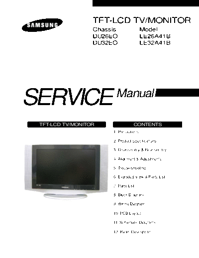
Image preview - the first page of the document
>> Download samsung_du26eo_chassis_le26a41b_lcd_tv_sm_183 documenatation <<
Text preview - extract from the document
TFT-LCD TV/MONITOR
Chassis Model
DU26EO LE26A41B
DU32EO LE32A41B
SERVICE Manual
TFT-LCD TV/MONITOR CONTENTS
1. Precautions
2. Product Specifications
3. Disassembly & Reassembly
4. Alignment & Adjustments
5. Troubleshooting
6. Exploded View & Parts List
7. Parts List
8. Block Diagram
9. Wiring Diagram
10. PCB Layout
11. Schematic Diagrams
12. Panel Description
Samsung Electronics Co.,Ltd.
This Service Manual is a property of 416, Maetan-3Dong, Yeongtong-Gu, Suwon City, Kyungki-Do,
Samsung Electronics Co., Ltd. Korea, 443-742
Any unauthorized use of Manual can be Printed in Korea
punished under applicable International P/N : BN82-00122B-00
and/or domestic law. URL : http://itself.sec.samsung.co.kr/
4 Alignments and Adjustments
4 Alignments and Adjustments
4-1 General Alignment Instuction
1. Usually, a color TV-VCR needs only slight touch-up adjustment upon installation.
Check the basic characteristics such as height, horizontal and vertical sync.
2. Use the specified test equipment or its equivalent.
3. Correct impedance matching is essential.
4. Avoid overload. Excessive signal from a sweep generator might overload the front-end
of the TV. When inserting signal markers, do not allow the marker generator to distort
test result.
5. Connect the TV only to an AC power source with voltage and frequency as specified on
the backcover nameplate.
6. Do not attempt to connect or disconnect any wire while the TV is turned on. Make sure
that the power cord is disconnected before replacing any parts.
7. To protect aganist shock hazard, use an isolation transform.
LE26A41B/LE32A41B 4-1
4 Alignments and Adjustments
4-2 Factory Mode Adjustments
4-2-1 Entering Factory Mode
1. To enter "Service Mode" Press the remote -control keys in this sequence :
- If you do not have Factory remote - control
- If you have Factory remote - control
- The buttons are active in the service mode.
1. Remote - Control Key : Power, Arrow Up, Arrow Down, Arrow Left
Arrow Right, Menu, Enter, Number Key(0~9)
2. Function - Control Key : Power, CH +, CH -, VOL +, VOL -,
Menu, TV/VIDEO(Enter)
4-2-2 Factory Mode Tree
T-DUO26OPEU-0033 07/22/2004 10:17:54
T-DUO32OPEU-0022 07/22/2004 10:17:54
T-DUO26OPEU-0033 07/22/2004 10:17:54
T-DUO32OPEU-0022 07/22/2004 10:17:54
T-DUO26OPEU-0033 07/22/2004 10:17:54
T-DUO32OPEU-0022 07/22/2004 10:17:54
4-2 LE26A41B/LE32A41B
4 Alignments and Adjustments
T-DUO26OPEU-0033 07/22/2004 10:17:54
T-DUO32OPEU-0022 07/22/2004 10:17:54
LE26A41B/LE32A41B 4-3
4 Alignments and Adjustments
T-DUO26OPEU-0033 07/22/2004 10:17:54
T-DUO26OPEU-0033 07/22/2004 10:17:54
T-DUO32OPEU-0022 07/22/2004 10:17:54
T-DUO32OPEU-0022 07/22/2004 10:17:54
T-DUO26OPEU-0033 07/22/2004 10:17:54
T-DUO26OPEU-0033 07/22/2004 10:17:54 T-DUO32OPEU-0022 07/22/2004 10:17:54
T-DUO32OPEU-0022 07/22/2004 10:17:54
4-4 LE26A41B/LE32A41B
4 Alignments and Adjustments
T-DUO26OPEU-0033 07/22/2004 10:17:54
T-DUO32OPEU-0022 07/22/2004 10:17:54
T-DUO26OPEU-0033 07/22/2004 10:17:54
T-DUO32OPEU-0022 07/22/2004 10:17:54
LE26A41B/LE32A41B 4-5
4 Alignments and Adjustments
T-DUO26OPEU-0033 07/22/2004 10:17:54
T-DUO32OPEU-0022 07/22/2004 10:17:54
4-6 LE26A41B/LE32A41B
4 Alignments and Adjustments
T-DUO26OPEU-0033 07/22/2004 10:17:54
T-DUO32OPEU-0022 07/22/2004 10:17:54
LE26A41B/LE32A41B 4-7
4 Alignments and Adjustments
4-8 LE26A41B/LE32A41B
4 Alignments and Adjustments
T-DUO26OPEU-0033 07/22/2004 10:17:54
T-DUO32OPEU-0022 07/22/2004 10:17:54
T-DUO26OPEU-0033 07/22/2004 10:17:54
T-DUO32OPEU-0022 07/22/2004 10:17:54
d/k
T-DUO26OPEU-0033 07/22/2004 10:17:54
T-DUO32OPEU-0022 07/22/2004 10:17:54
* Unless otherwise specifid, do not adjust data in Factory Mode.
* Data may be changed for display improvement.
LE26A41B/LE32A41B 4-9
4 Alignments and Adjustments
4-3 White Balance Adjustment
1. In factory mode (1, 3, 6), you can adjust the white balance.
2. As the adjustment and data values differ depending on input sources, different adjustments are requried for RF,
PC/DVI modes.
3. Optimum condition data for each mode are saved as default values. (Refer to Table 2, 3)
4. As the RF mode is applied with the same vlaues as for VIDEO and S-VIDEO, adjustment can be
made in any of RF, VIDEO and S-VIDEO modes.
Table 4-1. White Balance Setting Conditions
258 44(40) 1.5(1.2)
26(25) 0.7
32(35) 289 287 0.8(0.9)
( ) : ACER Panel
Table 4-2. Color Control Default Vlaue
Table 4-3. Color Control Default Vlaue
4-10 LE26A41B/LE32A41B
4 Alignments and Adjustments
4-3-1 Conditions for Measurement
1. On the basis of toshiba ABL pattern : High Light level (57 IRE)
- INPUT SIGNAL GENERATOR : MSPG-925LTH
* Mode NO 2 : 750X480@60 Hz
NO 6 : 1280X720@60 Hz
NO 21 : 1024X768@60 Hz
* Pattern NO 85 : 16 Color Bar Pattern
NO 16 : Toshiba ABL Pattern
2. Optical measuring device : CA210 (FL)
Please use the MSPG-925 LTH generator for model LW26A33W.
4-3-2 Method of Adjustment
1. Adjust the basic level of DTV and PC input signals.
a) Set the input to the mode in which the adjustment will be made (PC).
* Input signal - PC Mode : Model #21 (1024*768 Mode), Pattern #16 (Picture 4-1)
b) Enter factory Calibration, confirm the ADC data (PC Mode Only).
* ADC default value : Table 4-3.
Picture 4-1 Toshiba ABL Pattern
2. Adjust the white balance of RF, DTV and PC Modes.
a) Set the input to the mode in which the adjustment will be made (RF DTV PC).
* Input signal - VIDEO Mode : Model #1 (750*480 Mode), Pattern #16
- PC Mode : Model #21 (1024*768 Mode), Pattern #16
b) Enter factory color control, confirm the data.
LE26A41B/LE32A41B 4-11
4 Alignments and Adjustments
c) Adjust the low light. (Refer to table 1, 2 in adjustment position by mode)
- Adjust sub - Brightness to set the 'Y' value.
- Adjust red offset ('x') and blue offset ('y') to the color coordinates.
* Do not adjust green offset data.
Picture 4-2 Toshiba ABL Pattern
Low light
Measurement point
d) Adjust the high light. (Refer to table 1, 2 in adjustment position by mode)
- Adjust red gain ('x') and blue gain ('y') to the color coordinates.
* Do not adjust the green gain and sub-contrast (Y) data.
Picture 4-3 Toshiba ABL Pattern
High light
Measurement point
4-12 LE26A41B/LE32A41B
4 Alignments and Adjustments
4-3-3 Option Table
PanelType AMLCD
* The default settings are most recommended for Option Data. Each data may be adjusted.
4-3-4 PW565
* Below figures are for contrast adjustment of PW565 (IC602). Do not change the data.
LE26A41B/LE32A41B 4-13
4 Alignments and Adjustments
4-3-5 VPC 3230-MAIN
* Data may be adjusted.
4-3-6 ADC
*Adjust the R(Pr), G(Y), B(Pb) gain and offset to the basic level of DTV and PC Input signals.
4-14 LE26A41B/LE32A41B
4 Alignments and Adjustments
4-3-7 DNIe
* Control the specify item that a output signals of scalar (PW565).
* This data can be changed without notice.
4-3-8 MDIN-150
* Control the specify item that a output signals (RF, CVBS, S-VHS Modes) of MDIN-150 (IC405).
* This data can be changed without notice.
4-3-9 Test Pattern
* Use below test patters to demonstrate the image display of PW565 (IC602).
1) Luma Ramp (16 step)
2) Luma Ramp (128 Step)
3) White 16
4) White 240
5) Color Bar
6) RGB Ramp (32 Step)
4-3-10 Check sum
* XXXX : Displays the current check sum size of the MICOM.
(Varies depending on program update)
4-3-11 Reset
* Initializes the data in the MICOM. (Set to default value)
Use `Reset' to restore adjustmints made in Factory Mode to the original settings.
4-3-12 T_NPL26PEU_0130 03/08/2004 18:34:23
* Displays the MICOM program version
LE26A41B/LE32A41B 4-15
4 Alignments and Adjustments
4-4 How to use SW(FlashupgradNT) for LW26A33W Set program update
1. Store program practice file in new folder.
2. Connect Set and Jig Cable to execute Program Update.
(Refer to the Picture 4-4 attachment)
3. After completing the JIG Cable connection, store Update practice program (hex file 3EA) in new folder. (guiR,
romcode, factoryGui).
4. Click FlashupgradNT.exe icon 2 times and execute it.
(Upgrader OSD screen is marked)
Picture 4-4
5. Select OFull.inf in Flash.
(flaher, romcode, guir, factorygui items look in Files To)
Picture 4-5
4-16 LE26A41B/LE32A41B
4 Alignments and Adjustments
6. Click the "Flash" that is under right of OSD screen.
(if warning message comes out, Click the "Yes"(Y).)
Picture 4-6
7. After acting No.6, extract Set's Power Cable and connect it again.
8. During acting No.7, program Update sledding is marked sequentially on OSD screen.
9. After Program Update completion, act NO.7 again.
10. Program Update is completed.
3
4 2
1
Picture 4-7
1. Connect with PC Pattern Generator's output.
(Connect only when you want to see PC screen.)
2. Connect with JIG Output (15 pins) and PC Input (PC/DVI 24 pins) terminal.
3. Connect with COM Port1 of PC (9 Pins).
4. Connect 14V 4.5A Adaptor Cable.
LE26A41B/LE32A41B 4-17
4 Alignments and Adjustments
Memo
4-18 LE26A41B/LE32A41B
7_parts 2004.8.5 3:6 PM ` 7-1
7 Parts List
7 Parts List
You can search for updated part codes through ITSELF web site.
URL : http://itself.sec.samsung.co.kr/
7-1 Part Lists
Description Code No.(LE26A41B) Description Code No.(LE32A41B)
ASSY PCB MAIN BN94 - 00595V ASSY PCB MAIN BN94 - 00595Q
ASSY COVER FRONT BN90 - 00677D ASSY COVER FRONT BN90 - 00677K
ASSY COVER REAR BN90 - 00663V ASSY COVER REAR BN90 - 00663Y
LCD-PANEL BN07 - 00121A LCD-PANEL BN07 - 00172A
ASSY CHASSIS BN91 - 00814C ASSY CHASSIS BN91 - 00808Y
ASSY SHIELD BN91 - 00807V ASSY SHIELD BN91 - 00807X
ASSY BOX BN92 - 01133N ASSY BOX BN92 - 01133U
ASSY LABEL BN92 - 01044C ASSY LABEL BN92 - 01044U
REMOCON BN59 - 00412B REMOCON BN59 - 00412B
ASSY ACCESSORY BN92 - 01146E ASSY ACCESSORY BN92 - 01146P
ASSY PCB POWER_CH BN94 - 00443F ASSY PCB POWER_CH BN94 - 00443Z
ASSY PCB POWER_SUB PCB BN94 - 00444N ASSY PCB POWER_SUB PCB BN94 - 00444N
◦ Jabse Service Manual Search 2026 ◦ Jabse Pravopis ◦ onTap.bg ◦ Other service manual resources online : Fixya ◦ eServiceinfo