Service Manuals, User Guides, Schematic Diagrams or docs for : Samsung LCD TV LE32B450C4W XXC Samsung_LE19B450C4W-XXC-N65B Disassembly & Reassembly
<< Back | HomeMost service manuals and schematics are PDF files, so You will need Adobre Acrobat Reader to view : Acrobat Download Some of the files are DjVu format. Readers and resources available here : DjVu Resources
For the compressed files, most common are zip and rar. Please, extract files with Your favorite compression software ( WinZip, WinRAR ... ) before viewing. If a document has multiple parts, You should download all, before extracting.
Good luck. Repair on Your own risk. Make sure You know what You are doing.
Image preview - the first page of the document
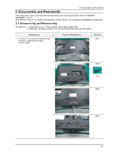
>> Download Disassembly & Reassembly documenatation <<
Text preview - extract from the document
                                                                                       3. Disassembly and Reassembly

3. Disassembly and Reassembly
This section of the service manual describes the disassembly and reassembly procedures for the LE19/22B45***,
LE26/32B45*** LCD TV.
    WARNING: This LCD TV contains electrostatically sensitive devices. Use caution when handling these components.

3-1. Disassembly and Reassembly
   Cautions: 1. Disconnect the LCD TV from the power source before disassembly.
             2. Follow these directions carefully; never use metal instruments to pry apart the cabinet.


                 Description                                    Picture Description                        Screws
 1. Place the TV face down on cushioned table.                                                              26/32"
    Remove 4 screws from the Stand.
    Remove stand.


                                                                                                            19/22"


                                                                                                            26/32"


                                                                                                            19/22"


                                                                                                                     3-1
3. Disassembly and Reassembly


                Description               Picture Description   Screws
                                                                 26/32"


                                                                 19/22"


2. Remove the 10 secrews of rear-cover.                          26/32"
   19" : 2, 22" : 3, 26"/32" : 10


                                                                 19/22"


3-2
                                                            3. Disassembly and Reassembly


                 Description               Picture Description               Screws
3. Lift up the rear-cover.                                                    26/32"


                                                                              19/22"


4. Remove the 5 screws of main board and                                      26/32"
   5 screws of IP board.
   And remove speaker and harness.


                                                                              19/22"


                                                                                       3-3
3. Disassembly and Reassembly


                  Description                         Picture Description   Screws
5. Remove the 2 screws of bracket TOP.
   Remove the 8 screws of bracket stand link.
   (TOP : 26/32" : 2, Stand link : 26" :6, 32" : 8)


6. Lift up the bracket TOP and stand link.                                   26/32"
   and remove 4 screws of bracket(22")


                                                                             19/22"


                                                                             26/32"


                                                                             19/22"


3-4
                                                                             3. Disassembly and Reassembly


                 Description                                Picture Description               Screws
7. Lift up the panel.                                                                          26/32"


                                                                                               19/22"


 Reassembly procedures are in the reverse order of disassembly procedures.


                                                                                                        3-5
◦ Jabse Service Manual Search 2026 ◦ Jabse Pravopis ◦ onTap.bg ◦ Other service manual resources online : Fixya ◦ eServiceinfo