Service Manuals, User Guides, Schematic Diagrams or docs for : Samsung LCD TV LE32R32B 08_Circuit Description

<< Back | Home

Most service manuals and schematics are PDF files, so You will need Adobre Acrobat Reader to view : Acrobat Download Some of the files are DjVu format. Readers and resources available here : DjVu Resources
For the compressed files, most common are zip and rar. Please, extract files with Your favorite compression software ( WinZip, WinRAR ... ) before viewing. If a document has multiple parts, You should download all, before extracting.
Good luck. Repair on Your own risk. Make sure You know what You are doing.


Image preview - the first page of the document
08_Circuit Description


>> Download 08_Circuit Description documenatation <<

Text preview - extract from the document
                                                       13 Circuit Descriptions


13 Circuit Descriptions
13-1 Block description
    Signal
    Power
                                          IP Board


  RF In (Air, Cable)

  Scart 1,2

  A/V

  S-Video                                  Main
                                           Board                Panel
  Component                                                     T-con
                                                                Board
  DVI-D

  PC


                                                     Speaker


                                          IR/LED

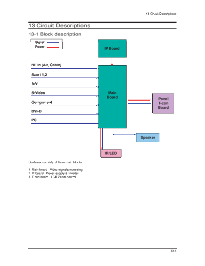
Bordeaux consists of three main blocks

1. Main board : Video signal processing
2. IP board : Power supply & Inverter
3. T-con board : LCD Panel control


                                                                         13-1
13 Circuit Descriptions


       Signal
       Power                               SMPS    INVERTER


  RF In (Air, Cable)

  Scart 1,2

  A/V

  S-Video                                  Main
                                           Board              Panel
  Component                                                   T-con
                                                              Board
  DVI-D

  PC


                                                    Speaker


                                          IR/LED


Bordeaux consists of three main blocks

1. Main board : Video signal processing
2. SMPS : Power supply
3. T-con board : LCD Panel control


13-2
                                                                                                            13 Circuit Descriptions

13-2 SMPS Board
13-2-1 32" Power Block


    Line                          PFC                                                                                     Inverter
                                                             Resonance
    Filter         AC           Switching       PFC                          Resonance                                     SMPS
                                                              Switching
    Part         Rectifier        Part         Rectifier                     Transformer     Output                         24V
                                                                Part
                                                                                             Rectifier
                                                                                              Part         DC/DC          Signal
                                                                                                          MC33167          5.4V
    AC Input                     PFC                          Resonance
(90Vac~264Vac)                 Controler                       Controller
                                                                                                                          Signal
                               TDA4863                          F9222L
                                                                                                                           13V


                                                                                                         Regulator        Sound
                                                                On/Off                                                   9V or 12V
                                                                Control


                                                                                                                          On/Off
                                                   Stand-By
                                                   Controller                                                            Stand-By
                                                   Viper22A                                                                 6V


13-2-2 32" SMPS Diagram


                                         PFC         PFC DC                           Current
                             Rectifier               Output                        Resonant Type ER3942
               EMI                                                                                                    INVERTER
             FILTER                                                                                                      24V
  INPUT
                                                    450V
   AC Input                                         120uF
  90V~264V                         TDA4863                                                                              Main
                                                                                                                        +13V

                                                            F9222L                                       Regulator

                                                                                                                        Sound
                                                                                                                      +9V / +12V
                                                       Trans EE2020
                                                                                              DC/DC                      V5D
                                                                                             Converter                  +5.4V
                                                              Viper22A
                                                                                                                      Stand-By
                                                                                                                         6V


                                                                         On/Off                                      Power On/Off
                                                                         Control                                        Signal


                                                                                                                                     13-3
13 Circuit Descriptions

13-2-3 BN96-03057A


                   Output Voltage               Output Current
 Output
                                                                     Load Characteristics   PCB Loc.      Usage         Remark
 Name
          Normal Regulation(%) Variable Range Min     Typical Peak


  24V     24.5V           4          23.52V   0.1V     3.0V   4.0V         Pulsating        Main B'D       Drive          -
                                    ~25.48V

                                                                                                        Drive, Logic,
                                     5.13V                                                  Main B'D                      -
  5.4V     5.4V           5                   0.1V     3.0V   5.0V         Constant                        Buffer,
                                    ~5.67V
                                                                                                       Image Digital


          12.7V           7          11.9V    0.01V    0.3V   0.5V         Constant                    Image Analog       -
  13V                                                                                       Main B'D
                                    ~13.7V

                          4          8.83V                                                                Sound           -
 Vamp      9.2V                               0.01V    0.3V   1.1V        Constant          Main B'D
                                    ~9.57V

                                     5.58V
 ST-BY     8.0V           5          ~8.5V    0.1V     0.3V   0.6V         Constant         Main B'D     Stand-by         -


13-2-4 BN96-03832A


                   Output Voltage               Output Current
 Output
                                                                     Load Characteristics   PCB Loc.      Usage         Remark
 Name
          Normal Regulation(%) Variable Range Min     Typical Peak


  24V     24.5V           4          23.52V   0.0V     5.0V   8.0V         Pulsating        Main B'D       Drive          -
                                    ~25.48V

                                                                                                        Drive, Logic,
                                     5.13V                                                  Main B'D                      -
  5.4V     5.4V           5                   0.0V     4.0V   5.0V         Constant                        Buffer,
                                    ~5.67V
                                                                                                       Image Digital


          12.7V           7          11.9V    0.0V     0.3V   0.5V         Constant                    Image Analog       -
  13V                                                                                       Main B'D
                                    ~13.7V

                          4         11.52V                                                                Sound           -
 Vamp      9.2V                               0.0V     0.5V   3.0V        Constant          Main B'D
                                    ~12.5V

                                     5.70V
 ST-BY     6.0V           5         ~6.30V    0.0V     0.3V   0.6V         Constant         Main B'D     Stand-by         -


13-4
                                                                                                    13 Circuit Descriptions


13-2-5 32" IP Board


   Power          EMI Filter          RFC                  SWITCHING        TRANSFORMER
   Input                            (switching,
  (AC90V                             Inductor)                                                 Rectifier     13.0V / 0.4A
  ~264V)          Rectifier
                                                                                               Rectifier     12.0V / 2.5A

                                                                                               Rectifier     5.4V / 43.5A
                                                  Feedback
                                                  Protection


                                     FWM                    FWM                Opto-            Feedback
                                  CONTROLLER             CONTROLLER           coupler           Protection


    VCC
   On/Off                                                                   TRANSFORMER
                                                          Stand-by                           Rectifier       6.2V / 0.4A
                                                        CONTROLLER
                                                          (Switch)

                                                                                               Feedback
                                                                                               Protection


                              SWITCHING            TRANSFORMER
                                                                            2nd
     Power
                                                                                          Balance
      Input                                                                                                   LAMP
                                                                          Resonant         Board
     (380V)


      UVLO            Gate
                     DRIVE

                                  Opto-Coupler /                                                              LAMP
   Opto-Coupler                       Pulse-
                                   Transformer
                                                                                        Voltage /
                                                                                        Current /
                                                                                         LAMP /
                                    CONTROLLER                                          Detection


     ON/OFF

       DIM                                                     Feedback


                                                                                                                           13-5
13 Circuit Descriptions

Memo


13-6


◦ Jabse Service Manual Search 2024 ◦ Jabse PravopisonTap.bg ◦ Other service manual resources online : FixyaeServiceinfo