Service Manuals, User Guides, Schematic Diagrams or docs for : Samsung LCD TV LE37C550 chassis N82A LE37C550J1W-XXH - N82A CHASSIS - 2010 Disassembly & Reassembly
<< Back | HomeMost service manuals and schematics are PDF files, so You will need Adobre Acrobat Reader to view : Acrobat Download Some of the files are DjVu format. Readers and resources available here : DjVu Resources
For the compressed files, most common are zip and rar. Please, extract files with Your favorite compression software ( WinZip, WinRAR ... ) before viewing. If a document has multiple parts, You should download all, before extracting.
Good luck. Repair on Your own risk. Make sure You know what You are doing.
Image preview - the first page of the document
>> Download Disassembly & Reassembly documenatation <<
Text preview - extract from the document
                                                                                       3. Disassembly and Reassembly

3. Disassembly and Reassembly
This section of the service manual describes the disassembly and reassembly procedures for the LE37C53*** LCD TV.
    WARNING: This LCD TV contains electrostatically sensitive devices. Use caution when handling these components.

3-1. Disassembly and Reassembly
   Cautions: 1. Disconnect the LCD TV from the power source before disassembly.
             2. Follow these directions carefully; never use metal instruments to pry apart the cabinet.
             3. If Rear-cover is made of metal, be careful not to scratch.

                 Description                                    Picture Description                          Screws
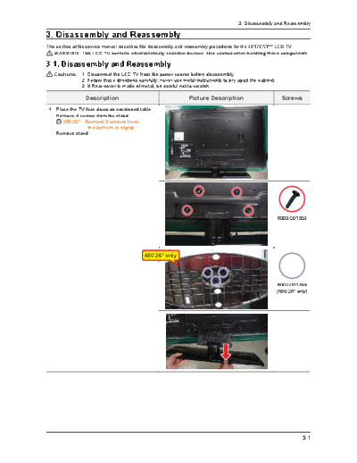
1. Place the TV face down on cushioned table.
   Remove 4 screws from the stand.
   N 450 26" : Remove 3 screws from
                 the bottom of stand.
   Remove stand.


                                                                                                           6003-001003


                                            450 26" only


                                                                                                           6002-001294
                                                                                                           (450 26" only)


                                                                                                                      3-1
3. Disassembly and Reassembly


                 Description                       Picture Description     Screws
2. Remove the screws of rear-cover.
    C5XX
   32" : Remove the 9 screws of rear-cover.
   37" : Remove the 13 screws of rear-cover.
   40" : Remove the 11 screws of rear-cover.
   46" : Remove the 14 screws of rear-cover.
                                                                         6003-001003
    C45X
   26" : Remove the 6 screws of rear-cover.
   32" : Remove the 8 screws of rear-cover.


                                                                         6002-001294
                                                                         (450 26" only)
3. Lift up the rear-cover.


4. Remove the left and right speaker.


5. Remove the 5 screws of main board.
   Remove the screws of SMPS board.
 C5XX
   32", 37" : Remove the 5 screws of rear-cover.
   40", 46" : Remove the 7 screws of rear-cover.
 C5XX
                                                                         6001-002284
   26", 32" : Remove the 5 screws of rear-cover.


                                                                         6003-001439
6. Remove the 5 screws of bracket stand link.
   Remove the screws of panel and front.
 C5XX
    32" : Remove the 4 screws of rear-cover.
    37" : Remove the 2 screws of rear-cover.
    40"/46" : Remove the 3 screws of rear-cover.
                                                                         6003-000337
 C5XX
   26" : Remove the 2 screws of rear-cover.
    32" : Remove the 4 screws of rear-cover.


                                                                         6003-001003


3-2
                                                                               3. Disassembly and Reassembly


                  Description                               Picture Description                 Screws
7. Lift up the stand link.


8. Lift up the panel.


 Reassembly procedures are in the reverse order of disassembly procedures.

Screw Size

   Code No.         A (mm)       B (mm)       C (mm)                    Q'ty

 6001-002284        8.3
◦ Jabse Service Manual Search 2026 ◦ Jabse Pravopis ◦ onTap.bg ◦ Other service manual resources online : Fixya ◦ eServiceinfo