Service Manuals, User Guides, Schematic Diagrams or docs for : Samsung Laptop NP-R55 Схема и сервис мануал на Samsung NP-R55 06_Disassembly & Reassembly

<< Back | Home

Most service manuals and schematics are PDF files, so You will need Adobre Acrobat Reader to view : Acrobat Download Some of the files are DjVu format. Readers and resources available here : DjVu Resources
For the compressed files, most common are zip and rar. Please, extract files with Your favorite compression software ( WinZip, WinRAR ... ) before viewing. If a document has multiple parts, You should download all, before extracting.
Good luck. Repair on Your own risk. Make sure You know what You are doing.


Image preview - the first page of the document
06_Disassembly & Reassembly


>> Download 06_Disassembly & Reassembly documenatation <<

Text preview - extract from the document
          .
  This Document can not be used without Samsung's authorization.


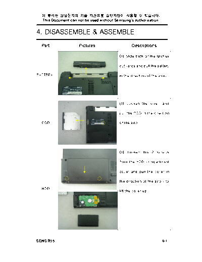
4. DISASSEMBLE & ASSEMBLE
  Part               Pictures                    Descriptions

                                          (1) Slide both of the latches

                                          outwards and pull the battery

BATTERY                                   in the direction of the arrow.


                                          (1) Loosen the screw and

                                          pull the ODD in the direction

  ODD                                     of the arrow.


                                          (1) Loosen the 2 screws

                                          from the HDD compartment

                                          cover and pull the cover in

                                          the direction of the arrow to
  HDD
                                          lift the cover up.


SENS R55                                                           4-1
          .
  This Document can not be used without Samsung's authorization.


4. DISASSEMBLE & ASSEMBLE
  Part                Pictures                     Descriptions

                                          (2) Pull the left and right
                                          hooks of the connector
                                          forward to lift the HDD.


  HDD


                                          (1) Insert a screw driver into
                                          the groove at the back and lift
                                          it up in the direction of the
                                          arrow. (Apply this step to both
                                          the left and right sides.)


  Main

 System


SENS R55                                                            4-2
          .
  This Document can not be used without Samsung's authorization.


4. DISASSEMBLE & ASSEMBLE
  Part                Pictures                    Descriptions

                                          (2) Loosen the 15 screws at
                                          the bottom of the computer.


                                          (3) Release the 2 hooks
                                          below the keyboard using a
                                          screwdriver.


  Main

 System


                                          (4) Lift the keyboard up and
                                          slightly pull the keyboard
                                          forward. Turn the keyboard
                                          over.


SENS R55                                                           4-3
          .
  This Document can not be used without Samsung's authorization.


4. DISASSEMBLE & ASSEMBLE
  Part                Pictures                     Descriptions

                                          (4) Lift the keyboard up and
                                          slightly pull the keyboard
                                          forward. Turn the keyboard
                                          over.


                                          (5) Separate all cables.


  Main

 System


                                          (6) Remove the cover and pull
                                          out the aerial cable.


SENS R55                                                             4-4
          .
  This Document can not be used without Samsung's authorization.


4. DISASSEMBLE & ASSEMBLE
  Part                Pictures                     Descriptions

                                          (6) Remove the cover and pull
                                          out the aerial cable.


                                          (7) Loosen the 2 screws and
                                          pull the LCD out.


  Main
                                          (8) Loosen the screw and lift
 System
                                          the back end of the main
                                          board forward slowly.


SENS R55                                                           4-5
          .
  This Document can not be used without Samsung's authorization.


4. DISASSEMBLE & ASSEMBLE
  Part                Pictures                     Descriptions

                                          (9) Loosen the five screws.


  Main

 System                                   (10) Lift the bottom end of the
                                          main    board    slightly   to
                                          separate      the        board
                                          completely.


                                          (1) Separate the USB board
                                          by pulling the USB board in
USB SUB                                   the direction of the arrow from
                                          the disassembled main board.
 BOARD


                                          (1) Push the hooks in the
                                          directions of the two arrows.
MINI PCI
                                          (2) Pull the Mini PCI in the
  CARD                                    direction of the arrow.


SENS R55                                                             4-6
          .
  This Document can not be used without Samsung's authorization.


4. DISASSEMBLE & ASSEMBLE
  Part                Pictures                     Descriptions

                                          (1) Slide both of the latches
                                          outwards and pull the battery
                                          in the direction of the arrow.


                                          (2) Loosen the 4 screws.


   LCD

  ASSY
                                          (3) Remove the cover and pull
                                          out the aerial cable.


SENS R55                                                             4-7
          .
  This Document can not be used without Samsung's authorization.


4. DISASSEMBLE & ASSEMBLE
  Part                Pictures                     Descriptions

                                          (4) Loosen the 2 screws and
                                          pull out the LCD.


                                          (5) Separate the 5 rubber
                                          parts.


   LCD
                                          (6) Loosen the screws that
  ASSY
                                           were under the rubber parts.


                                          (7) Lift the LCD panel up

                                          slowly from the bottom end

                                          with your hand.


SENS R55                                                           4-8
          .
  This Document can not be used without Samsung's authorization.


4. DISASSEMBLE & ASSEMBLE
  Part                Pictures                     Descriptions

                                          (8) Loosen the 4 screws.


                                          (9) Lift the LCD up holding the
                                          edge of the LCD with your
                                          hand.
   LCD

  ASSY


SENS R55                                                             4-9
          .
  This Document can not be used without Samsung's authorization.


4. DISASSEMBLE & ASSEMBLE
  Part                Pictures                     Descriptions

                                          (10) Loosen the 8 screws on
                                          both sides holding the edge of
                                          the LCD.


   LCD

  ASSY


                                          (11) Separate the bracket and
                                           turn the LCD over.


SENS R55                                                           4-10
          .
  This Document can not be used without Samsung's authorization.


4. DISASSEMBLE & ASSEMBLE
  Part                Pictures                     Descriptions

                                          (12) Pull the end of the cable
                                          on the lower part in the
                                          direction of the arrow to
                                          separate the cable from the
                                          inverter board.


                                          (13) Separate the LCD cable
                                          from the inverter board by
   LCD                                    pulling each of them in the
                                          direction of the respective
  ASSY                                    arrows.


                                          (14) Pull the LCD cable in the
                                          direction of the arrow to
                                          separate it from the LCD.


SENS R55                                                           4-11
          .
  This Document can not be used without Samsung's authorization.


4. DISASSEMBLE & ASSEMBLE
  Part                Pictures                    Descriptions

                                          (1) Loosen the screw on the
                                          memory compartment cover
                                          and remove the cover.


                                          (2) Pull the hooks outward.


 MEMORY


                                          (3) Separate the memory card
                                           by holding one side of the
                                           card.


SENS R55                                                           4-12


◦ Jabse Service Manual Search 2026 ◦ Jabse PravopisonTap.bg ◦ Other service manual resources online : FixyaeServiceinfo