Service Manuals, User Guides, Schematic Diagrams or docs for : Samsung Laptop NP-R60 Схема и сервис мануал на Samsung NP-R60 05_Disassembly_and_Reassembly

<< Back | Home

Most service manuals and schematics are PDF files, so You will need Adobre Acrobat Reader to view : Acrobat Download Some of the files are DjVu format. Readers and resources available here : DjVu Resources
For the compressed files, most common are zip and rar. Please, extract files with Your favorite compression software ( WinZip, WinRAR ... ) before viewing. If a document has multiple parts, You should download all, before extracting.
Good luck. Repair on Your own risk. Make sure You know what You are doing.


Image preview - the first page of the document
05_Disassembly_and_Reassembly


>> Download 05_Disassembly_and_Reassembly documenatation <<

Text preview - extract from the document
- This Document can not be used without Samsung's authorization -


4. Assembly and Disassembly

  Area                  Picture                                  Description


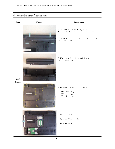
                                               1. AC adapter and battery have to be
                                               disassembled before dissembling system.


                                               2. Separate battery to point 2 direction after
                                               ove KNOB to point 1.


                                               3. Battery will be dissembled when push
                                               lightly upper side.


  Main
 System


                                               4. Remove screws on bottom side.

                                                   - M2.6 L8 : 16pcs
                                                   - M2 L7 : 2pcs
                                                   - M2 L4 : 3pcs


                                               5. Remove HDD door.

                                               6. Remove Memory door.

                                               7. Remove ODD.


                                             4-1
- This Document can not be used without Samsung's authorization -


4. Assembly and Disassembly

  Area                  Picture                                     Description


                                               8. Pull out to arrow side gripping handle to
                                               separate HDD from system.

                                               * Caution
                                                - Be careful when push the HDD to the rea
                                               r side.
                                               HDD must be removed before turning upside
                                               down the system.


                                               9. Remove Wireless LAN card after
                                               dissembling Wireless LAN Antenna.

                                                   - M2 L4 : 1pcs


                                               * Caution
                                                - PRAHA have only one Wireless Antenna.

  Main
 System

                                               10. Lift up Memory module by doing like
                                               point 1 and pull out module from socket.


                                               11. Remove screw of ODD side.
                                                 - M2 L3 : 1pcs


                                             4-2
- This Document can not be used without Samsung's authorization -


4. Assembly and Disassembly

  Area                  Picture                                 Description


                                               12. Bottom view after remove HDD, WLAN,
                                               Memory, ODD module.


                                               13. Remove top cover pushing hook of point
                                               1 hook and remove keyboard pushing hook
                                               of point

                                               * Caution
                                               Lift up Top cover after fully openning the lid.


  Main
 System

                                               14. Use tweezers, wooden cutter, '-' driver t
                                               o disassemble Topcover.


                                               15. Use tweezers, wooden cutter, '-' driver
                                               to disassemble Keyboard.

                                               * Caution
                                                1. Be careful of injury and scratch of Top s
                                               urface when use instruments.
                                                2. Don't lift up Keyboard highly.


                                             4-3
- This Document can not be used without Samsung's authorization -


4. Assembly and Disassembly

  Area                  Picture                                 Description


                                               16. Lift up FPC Connector cover like a
                                               picture and disassemble Keyboard FPC.

                                               * Caution
                                                Don't lift up FPC Connector cover highly.
                                                That may cause Connector crash.


                                               17. Disassemble 4 cables to remove Top ass
                                               y.


  Main
 System

                                               18. Disassemble Touchpad FFC after lifting
                                               up FPC Connector cover.


                                               * Caution
                                                Don't lift up FPC Connector cover highly.
                                                That may cause Connector crash.


                                               19. Disassemble Speaker Cable by pulling
                                               out the connector like a picture.


                                             4-4
- This Document can not be used without Samsung's authorization -


4. Assembly and Disassembly

  Area                  Picture                                  Description


                                               20. Disassemble LCD Cable by pull out left
                                               direction.


                                               * Caution
                                                 If lift up Top without disconnection of LCD
                                               Cable, that may cause LCD connector crash..


                                               21. Pull out the Wireless LAN Antenna from
                                               bottom side carefully.


  Main
 System

                                               22. Pull out the Wireless LAN Antenna from
                                               bottom side carefully.


                                               23. Disassembly LCD Ass'y from System after
                                               remove 2 screws.

                                                - M2.6 L8 : 2pcs


                                             4-5
- This Document can not be used without Samsung's authorization -


4. Assembly and Disassembly

  Area                  Picture                                  Description


                                               24. After disassembly LCD Ass'y.


                                               25. Pull out from right and disassemble top
                                               assy..


  Main
 System
                                               26. Remove 5pcs screws to disassemble
                                               Mainboard, FAN, Bluetooth and remove
                                               Bluetooth cable.

                                                - M2 L4 : 5pcs


                                               27. Disassemble FAN power cable and
                                               remove FAN.


                                             4-6
- This Document can not be used without Samsung's authorization -


4. Assembly and Disassembly

  Area                  Picture                                 Description


                                               28. Remove Mainboard from right side as
                                               like picture.


                                               * Caution
                                                If lift up from left side, that may cause
                                               crash of some ports


                                               29. Bottom after removing the Main Board.


  Main
 System

                                               30. Remove 7pcs screws to disassemble
                                               Heat Pipe and MDC.

                                                - M2 L4 : 1pcs
                                                - Special Screw : 6pcs


                                               31. Turn screw like a picture and lift up the
                                               CPU.

                                               * Caution
                                                Be care of not to bend CPU Pin.


                                             4-7
- This Document can not be used without Samsung's authorization -


4. Assembly and Disassembly

  Area                  Picture                                  Description


                                               32. Remove 2 screws to disassemble Express
                                               Frame.


                                                - M2 L6 : 2pcs


                                                   33. Lift up metal latch using driver to dis
                                                   assemble express frame.


                                                   * Caution
                                                    Be care of not to bend.


  Main
 System
                                               34. Pull out to right direction and
                                               disassemble express frame.


                                               39. The Main Board after removing the
                                               Thermal Duct, Heatsink, CPU, Express Frame,
                                               and MDC


                                             4-8
- This Document can not be used without Samsung's authorization -


4. Assembly and Disassembly

  Area                  Picture                                  Description


                                               1. Remove speaker.


   Top
  Ass'y                                        * Caution
                                                Touchpad module is fixed using by tape on
                                               Top


                                               1. Remove 5 screws after detaching rubber.

                                                - M2 L6 : 5pcs


                                               2. Use tweezers, wooden cutter or '-' driver
                                               when remove rubbers.

  LCD                                          * Caution
  Ass'y                                         Be careful of injury and scratch of LCD Fro
                                               nt surface when use instruments.


                                               3. Disassemble the LCD Front like a picture..

                                               * Caution
                                                Be careful of injury and scratch of LCD Fro
                                               nt surface when use instruments.


                                             4-9
- This Document can not be used without Samsung's authorization -


4. Assembly and Disassembly

  Area                  Picture                                  Description


                                               4. Disassemble the LCD Module and Inverter
                                               from LCD Back after removing 7 screws.

                                                - M2 L6 : 7pcs


                                               5. Disassemble the Bracket Upper after
                                               removing 2 screws.

                                                - M2 L4 : 2pcs


  LCD
  Ass'y
                                               6. Lift up the Knob latch after removing the
                                               Spring like a picture


                                               7. LCD Back after removing the LCD Module,
                                               Bracket Upper and Knob Latch.


                                            4-10
- This Document can not be used without Samsung's authorization -


4. Assembly and Disassembly

  Area                  Picture                                 Description


                                               8. Disassemble 3pcs connector from LCD
                                               Module.


                                               9. Disconnect the LCD Module from Inverter
                                               like a picture.


  LCD
  Ass'y

                                               10. isconnect the LCD Cable from Inverter
                                               like a picture.


                                               11. Disconnect the LCD Cable from LCD
                                               Module like a picture after detaching the
                                               silver adhesive.


                                            4-11
- This Document can not be used without Samsung's authorization -


4. Assembly and Disassembly

  Area                  Picture                                  Description


                                               12. Disassemble the LCD L, R Bracket after
                                               removing 6 screws.

                                                - M2 L3 : 6pcs

                                               * Caution
                                                Be care of not scratch the LCD surface whe
                                               n remove screws.


                                               13. LCD Module after removing LCD Cable, L,
                                               R Bracket and Inverter


   LCD
  Ass'y


                                            4-12


◦ Jabse Service Manual Search 2026 ◦ Jabse PravopisonTap.bg ◦ Other service manual resources online : FixyaeServiceinfo