Service Manuals, User Guides, Schematic Diagrams or docs for : Samsung Monitor Monitor Syncmaster 213T Chassis NB21BS samsung_syncmaster_213t_chassis_nb21bs
<< Back | HomeMost service manuals and schematics are PDF files, so You will need Adobre Acrobat Reader to view : Acrobat Download Some of the files are DjVu format. Readers and resources available here : DjVu Resources
For the compressed files, most common are zip and rar. Please, extract files with Your favorite compression software ( WinZip, WinRAR ... ) before viewing. If a document has multiple parts, You should download all, before extracting.
Good luck. Repair on Your own risk. Make sure You know what You are doing.
Image preview - the first page of the document
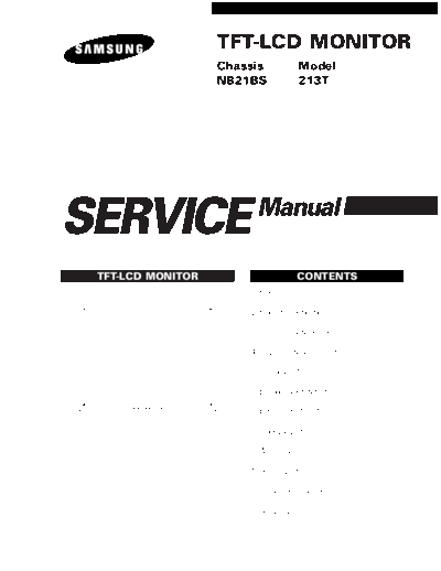
>> Download samsung_syncmaster_213t_chassis_nb21bs documenatation <<
Text preview - extract from the document
                   TFT-LCD MONITOR
                   Chassis              Model
                   NB21BS               213T


SERVICE                  Manual

 TFT-LCD MONITOR                        CONTENTS
                       1. Precautions

                       2. Product Specifications

                       3. Disassembly & Reassembly

                       4. Alignment & Adjustments

                       5. Troubleshooting

                       6. Exploded View & Parts List

                       7. Electrical Parts List

                       8. Block Diagram

                       9. Wiring Diagram

                       10. PCB Layout

                       11. Schematic Diagrams

                       12. Panel Description
Samsung Electronics Co.,Ltd.
416, Maetan-3Dong, Paldal-Gu, Suwon City, Kyungki-Do, Korea, 442-742.
Printed in Korea
P/N : BN82-00096A-00
http : //www.samsungmonitor.com (SyncMaster Worldwide)
http : //www.samsung-monitor.com (SyncMaster USA)
URL : http://ecms. samsungelectronics. com/
1 Precautions
Follow these safety, servicing and ESD precautions to prevent damage and to protect against potential hazards such as
electrical shock.

1-1 Safety Precautions
1-1-1 Warnings
                                                                                                       (READING SHOULD
                                                                                                      NOT BE ABOVE 0.5mA)
1.   For continued safety, do not attempt to modify the
     circuit board.
                                                                                                            LEAKAGE
2.   Disconnect the AC power and DC Power Jack                             DEVICE
                                                                           UNDER
                                                                                                            CURRENT
                                                                                                             TESTER
     before servicing.                                                     TEST
                                                                                         TEST ALL

1-1-2 Servicing the LCD Monitor                                                       EXPOSED METAL
                                                                                        SURFACES


1.   When servicing the LCD Monitor Disconnect the                              2-WIRE CORD

     AC line cord from the AC outlet.
2.   It is essential that service technicians have an                          ALSO TEST WITH
     accurate voltage meter available at all times. Check                      PLUG REVERSED
                                                                             (USING AC ADAPTER
     the calibration of this meter periodically.                             PLUG AS REQUIRED)                     EARTH
                                                                                                                  GROUND


1-1-3 Fire and Shock Hazard                                             Figure 1-1. Leakage Current Test Circuit
Before returning the monitor to the user, perform the
                                                              4.   With the unit completely reassembled, plug the AC
following safety checks:
                                                                   line cord directly into a 120V AC outlet. With the
1.   Inspect each lead dress to make certain that the              unit's AC switch first in the ON position and then
     leads are not pinched or that hardware is not                 OFF, measure the current between a known earth
     lodged between the chassis and other metal parts in           ground (metal water pipe, conduit, etc.) and all
     the monitor.                                                  exposed metal parts, including: metal cabinets,
2.   Inspect all protective devices such as nonmetallic            screwheads and control shafts. The current
     control knobs, insulating materials, cabinet backs,           measured should not exceed 0.5 milliamp. Reverse
     adjustment and compartment covers or shields,                 the power-plug prongs in the AC outlet and repeat
     isolation resistor-capacitor networks, mechanical             the test.
     insulators, etc.
3.   Leakage Current Hot Check (Figure 1-1): WARNING:         1-1-4 Product Safety Notices
     Do not use an isolation transformer during this test.
                                                              Some electrical and mechanical parts have special
     Use a leakage current tester or a metering system        safety-related characteristics which are often not
     that complies with American National Standards           evident from visual inspection. The protection they give
     Institute (ANSI C101.1, Leakage Current for              may not be obtained by replacing them with
     Appliances), and Underwriters Laboratories (UL           components rated for higher voltage, wattage, etc. Parts
     Publication UL1410, 59.7).                               that have special safety characteristics are identified by
                                                                ! on schematics and parts lists. A substitute
                                                              replacement that does not have the same safety
                                                              characteristics as the recommended replacement part
                                                              might create shock, fire and/or other hazards. Product
                                                              safety is under review continuously and new
                                                              instructions are issued whenever appropriate.


213T                                                                                                                        1-1
1 Precautions

1-2 Servicing Precautions
WARNING:          An electrolytic capacitor installed with the wrong polarity might explode.
Caution:          Before servicing units covered by this service manual, read and follow the Safety Precautions
                  section of this manual.
Note:             If unforeseen circumstances create conflict between the following servicing precautions and any of the
                  safety precautions, always follow the safety precautions.


1-2-1 General Servicing Precautions
1.    Always unplug the unit's AC power cord from the            4.   Check the insulation between the blades of the AC
      AC power source and disconnect the DC Power                     plug and accessible conductive parts (examples:
      Jack before attempting to:                                      metal panels, input terminals and earphone jacks).
      (a) remove or reinstall any component or assembly,         5.   Insulation Checking Procedure: Disconnect the
      (b) disconnect PCB plugs or connectors, (c) connect             power cord from the AC source and turn the power
      a test component in parallel with an electrolytic               switch ON. Connect an insulation resistance meter
      capacitor.                                                      (500 V) to the blades of the AC plug.
2.    Some components are raised above the printed                    The insulation resistance between each blade of the
      circuit board for safety. An insulation tube or tape            AC plug and accessible conductive parts (see
      is sometimes used. The internal wiring is                       above) should be greater than 1 megohm.
      sometimes clamped to prevent contact with
                                                                 6.   Always connect a test instrument's ground lead to
      thermally hot components. Reinstall all such
                                                                      the instrument chassis ground before connecting
      elements to their original position.
                                                                      the positive lead; always remove the instrument's
3.    After servicing, always check that the screws,                  ground lead last.
      components and wiring have been correctly
      reinstalled. Make sure that the area around the
      serviced part has not been damaged.


1-3 Electrostatically Sensitive Devices (ESD) Precautions
Some semiconductor (solid state) devices can be easily damaged by static electricity. Such components are commonly
called Electrostatically Sensitive Devices (ESD). Examples of typical ESD are integrated circuits and some field-effect
transistors. The following techniques will reduce the incidence of component damage caused by static electricity.

1.    Immediately before handling any semiconductor              6.   Do not remove a replacement ESD from its
      components or assemblies, drain the electrostatic               protective package until you are ready to install it.
      charge from your body by touching a known earth                 Most replacement ESDs are packaged with leads
      ground. Alternatively, wear a discharging wrist-                that are electrically shorted together by conductive
      strap device. To avoid a shock hazard, be sure to               foam, aluminum foil or other conductive materials.
      remove the wrist strap before applying power to            7.   Immediately before removing the protective
      the monitor.                                                    material from the leads of a replacement ESD,
2.    After removing an ESD-equipped assembly, place it               touch the protective material to the chassis or
      on a conductive surface such as aluminum foil to                circuit assembly into which the device will be
      prevent accumulation of an electrostatic charge.                installed.
3.    Do not use freon-propelled chemicals. These can                 Caution: Be sure no power is applied to the
      generate electrical charges sufficient to damage                         chassis or circuit and observe all
      ESDs.                                                                    other safety precautions.
4.    Use only a grounded-tip soldering iron to solder or
      desolder ESDs.                                             8.   Minimize body motions when handling
                                                                      unpackaged replacement ESDs. Motions such as
5.    Use only an anti-static solder removal device. Some             brushing clothes together, or lifting your foot from
      solder removal devices not classified as "anti-static"          a carpeted floor can generate enough static
      can generate electrical charges sufficient to damage            electricity to damage an ESD.
      ESDs.


1-2                                                                                                                     213T
2 Product Specifications
2-1 Specifications

              Item                                                       Description


LCD Panel                       TFT-LCD panel, RGB vertical stripe, normally black transmissive,
                                21.03-Inch (24.06-Inch) viewable, 0.27 mm pixel pitch

Scanning Frequency              Horizontal : 30 kHz ~ 81 kHz (Anolog)          30 kHz ~ 75 kHz (Digital)
                                Vertical : 56 Hz ~ 75 Hz (~SXGA), 60 Hz (UXGA) 56 Hz ~ 75 Hz (~SXGA), 60 Hz (UXGA)

Display Colors                  16.7 Million colors

Maximum Resolution              Horizontal : 1600 Pixels
                                Vertical : 1200 Pixels

Input Video Signal              Analog, 0.7 Vp-p
◦ Jabse Service Manual Search 2026 ◦ Jabse Pravopis ◦ onTap.bg ◦ Other service manual resources online : Fixya ◦ eServiceinfo