Service Manuals, User Guides, Schematic Diagrams or docs for : Samsung Monitor Monitor T23A950 03_disassembly_and_reassemble_E
<< Back | HomeMost service manuals and schematics are PDF files, so You will need Adobre Acrobat Reader to view : Acrobat Download Some of the files are DjVu format. Readers and resources available here : DjVu Resources
For the compressed files, most common are zip and rar. Please, extract files with Your favorite compression software ( WinZip, WinRAR ... ) before viewing. If a document has multiple parts, You should download all, before extracting.
Good luck. Repair on Your own risk. Make sure You know what You are doing.
Image preview - the first page of the document
>> Download 03_disassembly_and_reassemble_E documenatation <<
Text preview - extract from the document
                                                                                                  3. Disassembly and Assembly

3. Disassembly and Assembly
This section describes the disassembly and reassembly sequences for this monitor.


                                          As this monitor has parts that are sensitive to static electricity, be careful when
                                          handling them.


3-1. Disassembly
                                          1. Turn the monitor off before beginning the disassembly process.
                                          2. When disassembling the monitor, do not use any metal tools except for the
                                             provided jig.
                                          3. Disassemble the monitor carefully as directed in the following procedures.


                Description                                                          Photo
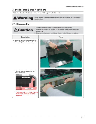
 1. Separate the front cover from the top
    first, pulling in the direction of the arrow.


     Internal locking tabs on the front
     and back covers.


     * These can be broken off easily during
       disassembly causing reassembly
       impossible.


                                                                                                                                3-1
3. Disassembly and Assembly


             Description                   Photo
2. Do not disassemble all and put the
   monitor down on the table as shown in
   the picture.


3-2
                                                  3. Disassembly and Assembly


             Description                  Photo
3. Remove the Rear cover from the upper
   side.


4. Disconnect the LVDS cable and
   function cable from the connector.


                                                                         3-3
3. Disassembly and Assembly


              Description          Photo
5. Remove the 12 screws.


      Screw


                    6003-001001
                       2 EA


                    6001-001470
                       5 EA


                     6001-001114
                        5 EA


6. Separate the panel from the
   BRACKET-PANEL.


3-4
                                                   3. Disassembly and Assembly


             Description                   Photo
7. Remove the 4 screws that connects the
   HINGE to the BRACKET-PANEL.


    Screw


                    6001-001114
                       4 EA


                                                                          3-5
3. Disassembly and Assembly


              Description              Photo
8. Separate the BRACKET-PANEL from
   the Stand.


9. Remove the 7 screws on the bottom
   side of the stand.


      Screw


                    6003-001086
                       7 EA


3-6
                                                   3. Disassembly and Assembly


             Description                   Photo
10. Separate the STAND TOP carefully.
    Be sure not to bend the TOP when you
    take the cover off.


11. Remove the 4 screws on the
    BRACKET-PCB.


    Screw


                    6003-000264
                       4 EA


                                                                          3-7
3. Disassembly and Assembly


                Description                                              Photo
12. Uncover the BRACKET-PCB and make
    all of the cables disconnected. Then
    separate the main board and the sub
    board.

      * New type of LVDS connector applied
        to 11' model.(Do uble locking)

      1. Flip up the locking tab on top of the
         connector.
      2. Squeeze the edge of the connector
         to release the second tab lock and
         gently pull the connector away.


13. Remove the Bluetooth and Fan as
    shown in the picture.


       Screw


                         6003-000109
                            3 EA


                         6003-000282
                            1 EA


 Reassembly procedures are in the reverse order of disassembly procedures.


3-8
                                                   3. Disassembly and Assembly


Screw Size

    Code No.     A (mm)   B (mm)   C (mm)   Q'ty

   6001-001114     8        6        4      9 EA

   6001-001470     8        3        3      5 EA

   6003-000264     6        6        3      4 EA

   6003-001001     6        8        3      2 EA

   6003-001086     6       12        3      7 EA

   6003-000109    5.5       8       2.6     3 EA

   6003-000282    6.3       8        3      1 EA


                                                                          3-9
3. Disassembly and Assembly


3-2. Precautions for Assembly
             Description                   Photo
1. Make HINGE stand perpendicularly
   as possible. It can help you assemble
   easily.


3-10
                                                  3. Disassembly and Assembly


            Description                   Photo
2. Be sure to keep the HINGE stand when
   attaching the PANEL to prevent the
   STAND TOP from getting speared.
   Ensure the bumps on the HINGE
   align perfectly with the red-circled
   holes before you assemble the ASSY
   P-REAR and fasten the screws.


                                                                        3-11
3. Disassembly and Assembly


              Description                             Photo
3. When you cover the Rear Cover, fit it in
   numerical order.
                                              3


                                              2   1


3-12
                                                   3. Disassembly and Assembly

3-3. Assembling the ASSY P-REAR
             Description                   Photo
1. Assemble the ASSY P-REAR starting
   from the marked area. (Otherwise, the
   assembly cannot proceed.)


2. Hook the SNAP marked in the image
   into the groove on the ASSY P-REAR.


3. Assemble the ASSY P-REAR by
   holding and pressing it at the marked
   area with your left hand as shown in
   the image.


                                                                         3-13
3. Disassembly and Assembly


             Description                  Photo
4. Assemble the FRONT into the REAR
   starting from the marked area.


5. Assemble the upper part of the REAR.


3-14
                                                 3. Disassembly and Assembly


             Description                 Photo
6. Press and fasten the corners of the
   REAR in a counterclockwise sequence
   as shown in the images.

   * Do not pound, but press or wipe,
     when fastening the corners.


                                                                       3-15
3. Disassembly and Assembly


             Description                    Photo
7. Double-check that the assembly is well
   done with no area loose, and stand the
   SET up.


3-16
◦ Jabse Service Manual Search 2026 ◦ Jabse Pravopis ◦ onTap.bg ◦ Other service manual resources online : Fixya ◦ eServiceinfo