Service Manuals, User Guides, Schematic Diagrams or docs for : Samsung Monitor Monitor 570DXN chassis BS57BPP samsung+570dxn-bs57bpp

<< Back | Home

Most service manuals and schematics are PDF files, so You will need Adobre Acrobat Reader to view : Acrobat Download Some of the files are DjVu format. Readers and resources available here : DjVu Resources
For the compressed files, most common are zip and rar. Please, extract files with Your favorite compression software ( WinZip, WinRAR ... ) before viewing. If a document has multiple parts, You should download all, before extracting.
Good luck. Repair on Your own risk. Make sure You know what You are doing.


Image preview - the first page of the document
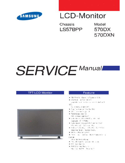
samsung+570dxn-bs57bpp


>> Download samsung+570dxn-bs57bpp documenatation <<

Text preview - extract from the document
                   LCD-Monitor
                   Chassis          Model
                   LS57BPP          570DX
                                    570DXN


SERVICE                      Manual


 TFT-LCD Monitor              Feature
                                          Samsung Electronics Co.,Ltd.
-This Service Manual is a property of
                                          416, Maetan-3Dong, Yeongtong-Gu, Suwon City, Gyeonggi-Do,
Samsung Electronics Co., Ltd.
                                          Korea, 443-742
Any unauthorized use of Manual can be     Printed in Korea
punished under applicable International   P/N : BN82-00135L-01
and/or domestic law.                      URL : http://itself.sec.samsung.co.kr/
                                                                  3. Alignment and Adjustments


3 Alignment and Adjustments
3-1 Service Mode

           3-1-1 Entering the Factory menu on the Main board(using REMOCON)

           - Power Off > MUTE > 1> 8 > 2 > Power On

           -When use the Factory remote control: INFO > Factory


                                                                                          3-1
3. Alignment and Adjustments


3-2 Service Mode Menu

                                           Auto-Color Adjusting

                                  Adjust color by R/G/B Offset and Gain

                                            Adjust Sharpness

                                         Improving display quality

                                  Noise Reduction, Fleshtone Correction

                                 Panel lifespan and replacement frequency

                                       Adjust H,V size and position

                                         Apply Spread Spectrum

                                              Factory Reset

                               Baudrate, nMFM operation status, Audio delay
                                         value, selection of country

                                  Check the version and date of MICOM


3-2
                                                           3. Alignment and Adjustments


- AutoColor Part


                                        PC analog Only ( 1024x768@60 16gray
                                        pattern)
                                        The Color Control properly operates only in
                                        the certain pattern with certain mode and the
                                        color warps in other patterns and modes.
                                        Also the proper color control is not supported
                                        in the mode other than XGA 60Hz.


                       Component ( 720p color bar pattern)
                       Color control operates normally only in certain modes
                       of certain patterns, but in other cases, the operation
                       may distort color.
                       Extreme caution needed.!!


- White Balance Part

                         Used for color control.
                         But excessive setting may saturate the color.
                         Extreme caution needed.!!


                                                                   On: Display factory
                                                                   adjusting value
                                                                   Off: Display default
                                                                   setting value


                               Register value in the Scaler
                               RED / BLUE / GREEN
                               Adjust the Gain and Offset


                                                                                   3-3
3. Alignment and Adjustments


- Sharpness Part (1)


                                  Adjusting the sharpness of displayed image.


- Sharpness Part (2)

                                           Scaling Filter Sharpness Control - Peaking Y / Peaking UV
                                           This adjusts the sharpness of luminance(Y) and color(UV).
                                           The bigger the number is in the range of 1~127, the clearer
                                           the picture is. The bigger the number is in the range of
                                           128~255, the more natural video is. Too high sharpness may
                                           cause the vivid noise.


                                           Noise Coring Control - Peaking Coring
                                           Display only the sharp large-edge without assuming the small-
                                           edge of the video as a noise and amplifying it.
                                           Noise Coring Out
                                                                           Assign the threshold value to
                                                                           improve the sharpness.


                               NonLinear Sharpness Control - Peaking Resion1/2 Threshold, Gain
                               Divide the frequency area and apply the different Gain for each area rather
                               than evenly apply the sharpness level over the whole image.


                                  Nonlinear Out


3-4
                                                         3. Alignment and Adjustments


- Enhancers Part

                          Adjust to display the clear and sharp image.
                          This function is used to adjust the appropriate value for
                          each target region. Change only when it is needed.


                         HLE : Horizontal Large Edge Enhancer
                         HDP : Horizontal Detail Processor
                         HCE : Horizontal Chroma Enhancer
                         VDP : Vertical Detail Processor

- Back End Part
                   The MPEG NR menu is used to reduce the Mosquito noise
                   and Gaussian noise. The Fleshtone menu is used to display
                   the natural skin color.


                                                                                 3-5
3. Alignment and Adjustments


- Panel Info Part


                               Display the panel use time and the number of change.


                               Time Reset : Press the menu button on the front panel for 5 seconds.


- AV Size Part


                               AV size, position Adjustment
                               H,V size / H,V Position


3-6
                                                                                            3. Alignment and Adjustments


- Spread Spectrum/Reset Part


                                          Spread Spectrum Adjustment
                                          The application status of Spread spectrum
                                          Amplitude and Period Setting


Reset : Factory Reset
Reset the setting on the Service Menu to the default setting.
Need to turn the Power On/Off after reset


- Option/Checksum Part
                                     Option Adjustment
                                     Baudrate Speed Setting (The default value is 9600.
                                     Change to 115200 when the code update on the main board is required.)
                                     Function Key Setting/Unsetting
                                     Option Setting in the Network part
                                     Audio delay Setting (Set for the video and audio synchronization.)
                                     The message display in the improper resolution mode Setting/Unsetting
                                     PC cable detect Setting/Unsetting
                                     DVI cable impedance matching setting
                                     DVI clock reset Setting/Unsetting
                                     DVI hot plug detect Setting/Unsetting
                                     FAN Speed Setting


Checksum
The 4 digit serial number regarding the micom code is
displayed if you select this.


                                                                                                                    3-7
3. Alignment and Adjustments


3-3 DDC Input Process
Connecting D-sub cable between the parallel port(printer port) of computer and Monitor.


       PC


            Connecting to the parallel
            port of computer
                                                     Connecting to Monitor


3-8
                                                                               3. Alignment and Adjustments


- DDC Input Process
(DDC file name : SM570DXA1.DDC / SM570DXD1.DDC)

The DDC input is available after entering the Service Mode.: Cancel the DDC Protection.


1.   Open the file.
2.   Select Port 1 (D-SUB) / Select Port 2(DVI)
3.   Select the DDC file.
4.   Click the Next(OK) button.


                                                        5


5: Input the monitor serial number and press Enter.
Input Analog and repeat 2~5 times when input Digital.


                                                                                                       3-9
3. Alignment and Adjustments


3-4 MDC(Multi Display Control) Program

                               1. Run the SETUP. EXE file.


                               2. Select I Agree.


                               3. Select NEXT.


                               4. Select Install.


3-10
                  3. Alignment and Adjustments


5. "Yes" Click.


6. "OK" Click.


                                         3-11
3. Alignment and Adjustments


3-5 MDC(Multi Display Control) Program_How to use
- Connect the serial port of the PC and Beethoven Board with the RS232C cable.

- Option in the Factory Menu : Check if BaudRate is set to 9600


                                                      A Multiple Display Control (MDC) is an application
                                                      allowing various displays to be easily and
                                                      simultaneously operated on a PC. RS-232C, a
                                                      standard of serial communication, is used for the
                                                      communication between a PC and a display.
                                                      Therefore, a serial cable should be connected
                                                      between the serial port on a PC and the serial port
                                                      on a display.
                                                      Refer to the diagram.


- Start- Main Window
 Click Start > Program > Multiple Display Control to start the program.
 Select a set to see the volume of the selected set within the slider.

                                                           1. Click the main icons to switch into each
                                                              screen.
                                                           2. Allows you to enable or disable the remote
                                                              control signal receiving function of the display
                                                              unit.
                                                           3. Use to lock monitor functions.
                                                           4. Use to change the port. The default port is
                                                              COM1.
                                                           5. Use Select All and Clear All buttons to select
                                                              or clear all displays.
                                                           6. Use Grid to view brief information on selected
                                                              display.

                                                           The remote control Enable/Disable function
                                                           operates whether or not the power is On/Off,
                                                           and this applies to all displays connected to the
                                                           MDC. However, all displays return to the default
                                                           setting with the remote control receiving function
                                                           enabled regardless of the status at the time the
                                                           MDC is shut down


3-12
                                                                     3. Alignment and Adjustments

- Start-Port Selection

                                             1. Multiple Display Control is originally set to
                                                COM1.
                                             2. If the port other than COM 1 is used, any port
                                                between COM1 to COM4 is selectable.
                                             3. The port connected to the monitor and serial
                                                cable needs to be assigned with the correct
                                                name for the communications.
                                             4. Once the port is selected, it is stored and
                                                used for the next program.


- Power Control

                                             1. Click Power Control of the main icons to display the
                                               Power Control window.
                                             - Info Grid shows some basic information necessary
                                     6
                                               for Power Control.
                                             1) Power Status
                                     7       2) Input Source
              1   2      3   4   5       8   3) Image Size
                                             4) On Timer Status
                                             5) Off Timer Status
                                             2. Use the Select All button or Check Box to choose a
                                               display to control.
                                               Power Control allows you to control functions
                                               regarding the power of the selected display on the
                                               menu.
                                             6) Power On/Off
                                               Turns the power of the selected display on or off.
                                             7) Volume
                                                Adjust the volume of the selected display.
                                                The appropriate volume for the selected set is
                                               displayed as you select a set.
                                                (When you cancel the selection or choose Select
                                               All, the volume returns to the default value 10.)
                                             8) Mute On/Off
                                               Turns on or off the Mute function of the selected
                                               monitor. The Power Control feature is available for
                                               all connected monitors.


                                             - The Volume Control and Mute features are
                                               available only for the displays whose power
                                               status is ON.


                                                                                               3-13
3. Alignment and Adjustments

-Input Source Control
1. Click Input Source of the main icons to display the Input Source control window.
   Click Select All or use Check Box to select a display to control.

                                                          - Info Grid shows some basic information necessary to Input
                                                            Source Control.
                                                          1) PC
                                                             Changes the Input Source of the selected display to PC.
                                                          2) BNC
                                                             Changes the Input Source of the selected display to BNC.
                                                          3) DVI
                                                             Changes the Input Source of the selected display to DVI.
                                                          4) TV
                                                             Changes the Input Source of the selected display to TV.
                                                          5) AV
                                                             Changes the Input Source of the selected display to AV.
                                                          6) S-Video
                                                            Changes the Input Source of the selected display to
                                                             S-Video.
                                                          7) Component
                                                             Changes the Input Source of the selected display to
                                                          Component.
                                                          8) MagicNet
                                                            The MagicNet input can be changed only in the MagicNet
                                                            mode.


                                                          - The Input Source Control feature is available only for
                                                            the display whose power status is ON.


-Image Size Control - PC, BNC, DVI
1. Click Image Size of the main icons to display the Image Size control window.

                                                          - Info Grid shows some basic information necessary to
                                                            Image Size Control.
                                                          1) Power
                                          4                  Shows the power status of the current display.
                                                          2) Image Size
               1    2          3                             Shows the current Image Size of the display in use.
                                                          3) Input Source
                                                            Shows the current Input Source of the display in use.
                                                            Info Grid displays only the displays whose Input Source is
                                                            PC, BNC, or DVI.
                                                          4) When you click Image Size, the PC, BNC, and DVI tabs
                                                            first appear.
                                                            This feature allows you to control Image Size for PC, BNC,
                                                            or DV.


                                                          - Image Size Control is available only for the displays
                                                            for whose power status is ON.


3-14
                                                                                     3. Alignment and Adjustments


-Image Size Control - Video Source
1. Click Image Size of the main icons to display the Image Size window.

                                                          - Info Grid shows some basic information necessary to
                                                            Image Size Control.
                                                          1) Click the Video Source tab to adjust the Image Size of
                                          4                 AV, S-Video, TV, Component, or DVI(HDCP). Click Select
                                                            All or use Check Box to select a display to control.
              1    2         3                            2) Info Grid displays only the display having AV, S-Video,
                                                            TV, Component, or DVI(HDCP) as input source
                                                          3) Adjust the Image Size of the display.
                                                            If the input signal for the component or DVI(HDCP) is
                                                            720p or 1080, Zoom1 and Zoom are not available.


                                                          - The Image Size Control feature is available only for
                                                            the displays whose power status is ON.


-Time Control
1. Click Time of the main icons to display the Time Control window.

                                                          - Info Grid shows some basic information necessary to Time
                                                            Control.
                                                          1) Current Time
                                          4                 Set the current time for the selected display (PC Time).
                                                            Set the PC time before you change the current time.
              1    2         3                            2) On Time Setup
                                                            Set the hour, minute, AM/PM of On Time, Status, Source,
                                                            and Volume of the selected display.
                                                          3) Off Time Setup
                                                            Set the hour, minute,, and AM/PM, and Status for Off
                                                            Timer of the selected display.
                                                          4) Shows the On Timer settings.
                                                          5) Shows the Off Timer settings.


                                                          - Time Control is available only for the displays for
                                                            whose the power status is ON.


                                                                                                                   3-15
3. Alignment and Adjustments


-PIP Control - PIP Size
1. Click PIP of the main icons to display the PIP control window.


                                                           - Info Grid shows some basic information necessary to PIP
                                                             Size Control.
                                                           1) PIP Size
                                                              Shows the current PIP Size of the display in use.
                                          4
                                                           2) OFF
                                                               Turns off the PIP of the selected display.
               1    2          3                           3) Large
                                                             Turns on the PIP of the selected display and changes the
                                                             size to Large.
                                                           4) Small
                                                             Turns on the PIP of the selected display and changes the
                                                             size to Small.
                                                           5) Double1
                                                             Turns on the PIP of the selected display and changes the
                                                             size to Double 1.
                                                           6) Double2
                                                             Turns on the PIP of the selected display and changes the
                                                             size to Double 2.
                                                           7) Double3
                                                             Turns on the PIP of the selected display and changes the
                                                             size to Double 3.


                                                           - PIP Control is available only for the displays whose
                                                             power status is ON.
                                                           - The set with the input source Component is not
                                                             displayed on Info Grid.


3-16
                                                                                                    3. Alignment and Adjustments

-PIP Control - PIP Source
1. Click PIP of the main icons to display the PIP control window.

                                                                        - Info grid shows some basic information necessary to PIP
                                                                          Source Control.
                                                                        1) PIP Source
                                                                          Click the PIP Source tab to display the PIP Source list.
                                                                          PIP Source can be controlled only when the power of the
                                                                          monitor is turned on.
                                                                        2) PC
                                                                            Changes the PIP source of the selected display to PC.
                                                                        3) BNC
                                                                          Changes the PIP source of the selected display to BNC.
                                                                        4) DVI
                                                                          Changes the PIP source of the selected display to DVI.
                                                                        5) TV
                                                                          Changes the PIP source of the selected display to TV.
                                                                        6) AV
                                                                          Changes the PIP source of the selected display to AV.
                                                                        7) S-Video
Some of the PIP Sources may not be available for selection                Changes the PIP source of the selected display to
depending on the input source type of the Main Screen.                    S-Video.
                                                                        8) Component
The PIP control feature is available only for the displays whose          Changes the PIP source of the selected display to
power status is ON and the PIP function is set to ON.                     Component.


- Setting Control - Picture
1. Click Settings of the main icons to display the Settings Control screen.

                                                                        - Info Grid shows some basic information necessary to
                                                                          Setting Control. When each function is selected, the set
                                                                          value of the selected function is displayed in the slide. As
                                                                          you select Select All, the value is returned to the default
                                                                          setting (50).
                                                                          Changing a value in this screen will automatically change
                                                                          the mode to "CUSTOM."
                                                                        1) Picture
                                                                          Available only for TV, AV, S-Video, Component, and
                                                                          DVI(HDCP).
                                                                        2) Contrast
                                                                           Adjusts Contrast of the selected display.
                                                                        3) Brightness
                                                                          Adjusts Brightness of the selected display.
                                                                        4) Sharpness
                                                                          Adjusts Sharpness of the selected display.
                                                                        5) Color
This feature is available only for the displays whose power status is      Adjusts Color of the selected display.
ON and if no selection is made, the factory default is displayed.       6) Tint
                                                                          Adjusts Tint of the selected display.
                                                                        7) Color Tone
                                                                          Adjusts Color Tone of the selected display.


                                                                                                                                 3-17
3. Alignment and Adjustments

-Setting Control - Picture PC
1. Click Setting of the main icons and select the Picture PC tab to display the Setting Control window.

                                                                        - Info Grid shows some basic information necessary to
                                                                          Setting Control. When each function is selected, the set
                                                                          value of the selected function is displayed in the slide. As
                                                                          you select Select All, the value is returned to the default
                                                                          setting (50).
                                                                          Changing a value in this screen will automatically change
                                                                          the mode to "CUSTOM."
                                                                        1) Picture PC
                                                                           Available only for PC, BNC, and DVI.
                                                                        2) Contrast
                                                                           Adjusts Contrast of the selected display.
                                                                        3) Brightness
                                                                           Adjusts Brightness of the selected display.
                                                                        4) Red
                                                                           Adjusts Red Color of the selected display.
                                                                        5) Green
                                                                           Adjusts Green Color of the selected display.
This feature is available only for the displays whose power status is   6) Blue
ON and if no selection is made, the factory default is displayed.          Adjusts Blue Color of he selected display.


-Setting Control - Audio
1. Click Settings of the main icons and select the Audio tab to display the Setting Control window.

                                                                        - Info Grid shows some basic information necessary to
                                                                          Setting Control. When each function is selected, the set
                                                                          value of the selected function is displayed in the slide. As
                                                                          you select Select All, the value is returned to the default
                                                                          setting (50).
                                                                          Changing a value in this screen will automatically change
                                                                          the mode to "CUSTOM."
                                                                        1) Audio
                                                                          Controls audio setting for all input sources.
                                                                        2) Bass
                                                                          Adjusts Bass of the selected display.
                                                                        3) Treble
                                                                          Adjusts Treble of the selected display.
                                                                        4) Balance
                                                                           Adjusts Balance of the selected display.
                                                                        5) SRS TSXT
                                                                          Turns the SRS Trusurround XT function of the selected
This feature is available only for the displays whose power status in     display On/Off.
IN and if no selection is made, the factory default is displayed.       6) Sound Select
The MagicNet Input operates only in MagicNet models.                      Select either Main or Sub when the PIP of the selected
                                                                          display is turned On.


3-18
                                                                                       3. Alignment and Adjustments

-Setting Control - Image Lock
1. Click Settings of the main icons and select the Image tab to display the Setting Control window.

                                                           - Info Grid shows some basic information necessary to
                                                             Image Lock.
                                                           1) Image Lock
                                                             Available only the controls for PC and BNC.
                                                           2) Coarse
                                                             Adjusts Coarse of the selected display.
                                                           3) Fine
                                                             Adjusts Fine of the selected display.
                                                           4) Position
                                                             Adjusts Position of the selected display.
                                                           5) Auto Adjustment
                                                             Automatically adjusts the screen.


                                                           - This feature is available only for the displays whose
                                                             power status is ON.


-Maintenance Control - Lamp Control
1. Click Maintenance of the main icons and select the Lamp Control tab to display the Maintenance Control
    window.


                                                           - Info Grid shows some basic information necessary to
                                                             Maintenance Control.
                                                           1) Lamp control
                                                              Adjusts the brightness of the lamp.
                                                           2) Auto Lamp Control
                                                             Automatically adjusts the backlight of the selected display
                                                             at a specified time. The Auto Lamp Control automatically
                                                             turns off if you adjust using the Manual Lamp Control.
                                                           3) Manual Lamp Control
                                                             Allows you to adjust the backlight of the selected display
                                                             regardless of the time.
                                                             The Manual Lamp Control automatically turns off if you
                                                             adjust using the Manual Lamp Control.


                                                           - The Maintenance Control feature is available only for the
                                                             displays whose Power Status is ON.


                                                                                                                   3-19
3. Alignment and Adjustments

-Maintenance Control - Lamp Control
1. Click Maintenance of the main icons and select the Scroll tab to display the Maintenance Control.

                                                                    1) Screen Scroll
                                                                      Eliminates the afterimages that can result when the still
                                                                      image is displayed for prolonged periods. Use Interval to
                                                                      set the repeat cycle by time unit and use Second to set the
                                                                      repeat cycle by second unit. Select one of 4 types- Scroll,
                                                                      Pixel, Bar, Eraser.


                                                                    - The Maintenance Control feature is available only for the
                                                                      displays whose power status in ON.


-Maintenance Control - Video Wall
1. Click Maintenance of the main icons and select the Wall tab to display the Maintenance Control window.

                                                                    1) Video Wall
                                                                      A Video Wall is a set of video screens that are connected
                                                                      together, so that each screen shows a part of the whole
                                                                      picture or so that the same picture is repeated on each
                                                                      screen.
                                                                    2) Video Wall (Screen Divider)
                                                                      You can select a number of screens with a different layout
                                                                      when dividing.
                                                                      2*2                      3*3


                                                                      4*4


3) On / Off
  Turns On or Off the Video Wall function of the selected                                                              2*1
  display.
4) Format
  The format can be selected to see a divided screen.


                                                                   1*2                                                5*1


         Full                                     Natural

This feature is available only for the displays whose power
status in IN and if no selection is made, the factory default is   1*5
displayed.
The Malignant Input operates only in MagicNet models.


3-20
                                                                                             3. Alignment and Adjustments


-Troubleshooting

1. The display you wish to control does not appear on the Power Control Info Grid
   - Check the connection of RS232C. (Check if it is properly connected to the Com1 port)
   - Check the displays to see if any of the other displays connected have the same ID. If more than one
     displays have the same ID, those displays are not properly detected by the program due to data conflict.
   - Check if the Display Set ID is a number between 1 and 10. (Adjust using the Display menu)


note : A Display Set ID must be a value between 1 and 10.
      If the value is out of the range, the MDC system cannot control the display.


2. The display you wish to control does not appear on the other Control Info Grids
   - Check to see if the display power is ON. (You can check this in Power Control Info Grid)
   - Check if you can change the input source of the display.


3. The dialogue box appears repeatedly.
   - Check to see if the display you wish to control is selected.


4. Both On Timer and Off Timer have been set but different time is showing.
   - Apply current time to synchronize the display clocks.


5. The remote may not function properly when you turn off the remote Function, disconnect the RS-232C
   cable, or exit the program in an Irregular manner. Rerun the program and turn the remote function
   again to Restore normal functions.


note : This program may malfunction due to problems in communication circuits or interference from electronic
      appliances nearby.


Settings Value Display In Multiple Display Mode

When there are more than one displays connected, the settings values are displayed as follows.
1. No selection: Displays the Factory Default Value.
2. Selected one display: Fetches and displays the settings value for the selected display.
3. Selected one display (ID1) and add another display (ID3): The program, which was displaying the settings value of
ID 1, fetches and displays the value of ID3.
4. Selected all sets using Select All: Returns to the Factory Default Value.


                                                                                                                    3-21
3. Alignment and Adjustments


3-6 Updating the program - MAIN
-. How to connect
1.Connect the serial port of the PC and the input serial port of Beethoven Board with the RS232C cable.
2. Option in the Factory Menu : Check if BaudRate is set to 115200.


                                                                      RS-232C, a standard of serial communication, is used for the
                                                                      communication between a PC and a display. Therefore, a serial
                                                                      cable should be connected between the serial port on a PC and
                                                                      the serial port on a display.
                                                                      Refer to the diagram.


Run the .exe file and press the 


◦ Jabse Service Manual Search 2026 ◦ Jabse PravopisonTap.bg ◦ Other service manual resources online : FixyaeServiceinfo