Service Manuals, User Guides, Schematic Diagrams or docs for : Samsung Microwave ME21F707MJT_AA Service Manual ME21F707MJT_S-MANUAL
<< Back | HomeMost service manuals and schematics are PDF files, so You will need Adobre Acrobat Reader to view : Acrobat Download Some of the files are DjVu format. Readers and resources available here : DjVu Resources
For the compressed files, most common are zip and rar. Please, extract files with Your favorite compression software ( WinZip, WinRAR ... ) before viewing. If a document has multiple parts, You should download all, before extracting.
Good luck. Repair on Your own risk. Make sure You know what You are doing.
Image preview - the first page of the document
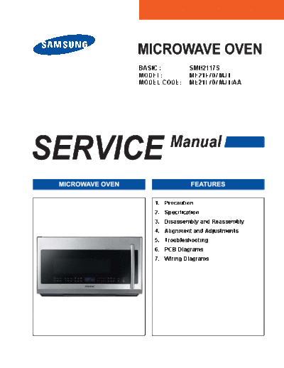
>> Download ME21F707MJT_S-MANUAL documenatation <<
Text preview - extract from the document
BASIC : SMH2117S
MODEL: ME21F707MJT
MODEL CODE: ME21F707MJT/AA
1. Precaution
3. Disassembly and Reassembly
4. Alignment and Adjustments
5. Troubleshooting
6. PCB Diagrams
7. Wiring Diagrams
1. Precaution . . . . . . . . . . . . . . . . . . . . . . . . . . . . . . . . . . . . . . . . . . . . . . . . . . . . . . . . . . . . . . . . . . . . . . . . . . . . . . . . . . . . . . . . . . . . 3
1-1 Safety precautions . . . . . . . . . . . . . . . . . . . . . . . . . . . . . . . . . . . . . . . . . . . . . . . . . . . . . . . . . . . . . . . . . . . . . . . . . . . . . . . . . . 4
1-2 Special High Voltage Precautions . . . . . . . . . . . . . . . . . . . . . . . . . . . . . . . . . . . . . . . . . . . . . . . . . . . . . . . . . . . . . . . . . . . . . . . 5
.........................................................................................6
2-1 Features . . . . . . . . . . . . . . . . . . . . . . . . . . . . . . . . . . . . . . . . . . . . . . . . . . . . . . . . . . . . . . . . . . . . . . . . . . . . . . . . . . . . . . . . . . 6
................................................................................6
2-3 Accessory . . . . . . . . . . . . . . . . . . . . . . . . . . . . . . . . . . . . . . . . . . . . . . . . . . . . . . . . . . . . . . . . . . . . . . . . . . . . . . . . . . . . . . . . . 8
3. Disassembly and Reassembly . . . . . . . . . . . . . . . . . . . . . . . . . . . . . . . . . . . . . . . . . . . . . . . . . . . . . . . . . . . . . . . . . . . . . . . . . . . . 9
3-1 Replacement of High Voltage Transformer . . . . . . . . . . . . . . . . . . . . . . . . . . . . . . . . . . . . . . . . . . . . . . . . . . . . . . . . . . . . . . . 10
3-2 Replacement of Magnetron . . . . . . . . . . . . . . . . . . . . . . . . . . . . . . . . . . . . . . . . . . . . . . . . . . . . . . . . . . . . . . . . . . . . . . . . . . . 12
3-3 Replacement of Fan Motor . . . . . . . . . . . . . . . . . . . . . . . . . . . . . . . . . . . . . . . . . . . . . . . . . . . . . . . . . . . . . . . . . . . . . . . . . . . 13
3-4 Replacement of Door Assembly . . . . . . . . . . . . . . . . . . . . . . . . . . . . . . . . . . . . . . . . . . . . . . . . . . . . . . . . . . . . . . . . . . . . . . . 14
3-5 Replacement of Fuse . . . . . . . . . . . . . . . . . . . . . . . . . . . . . . . . . . . . . . . . . . . . . . . . . . . . . . . . . . . . . . . . . . . . . . . . . . . . . . . 16
3-6 Replacement of Drive Motor . . . . . . . . . . . . . . . . . . . . . . . . . . . . . . . . . . . . . . . . . . . . . . . . . . . . . . . . . . . . . . . . . . . . . . . . . . 16
3-7 Removal of Stirrer . . . . . . . . . . . . . . . . . . . . . . . . . . . . . . . . . . . . . . . . . . . . . . . . . . . . . . . . . . . . . . . . . . . . . . . . . . . . . . . . . . 17
3-8 Replacement of Control Circuit Board (MAIN PBA) . . . . . . . . . . . . . . . . . . . . . . . . . . . . . . . . . . . . . . . . . . . . . . . . . . . . . . . . 18
3-8-1 MAIN PBA . . . . . . . . . . . . . . . . . . . . . . . . . . . . . . . . . . . . . . . . . . . . . . . . . . . . . . . . . . . . . . . . . . . . . . . . . . . . . . . . . . . 18
3-8-2 SUB Module . . . . . . . . . . . . . . . . . . . . . . . . . . . . . . . . . . . . . . . . . . . . . . . . . . . . . . . . . . . . . . . . . . . . . . . . . . . . . . . . . . 19
3-9 Replacement of Cooktop lamp . . . . . . . . . . . . . . . . . . . . . . . . . . . . . . . . . . . . . . . . . . . . . . . . . . . . . . . . . . . . . . . . . . . . . . . . 20
3-10 Replacement of Oven Light . . . . . . . . . . . . . . . . . . . . . . . . . . . . . . . . . . . . . . . . . . . . . . . . . . . . . . . . . . . . . . . . . . . . . . . . . . 21
4. Alignment and Adjustments . . . . . . . . . . . . . . . . . . . . . . . . . . . . . . . . . . . . . . . . . . . . . . . . . . . . . . . . . . . . . . . . . . . . . . . . . . . . . 22
4-1 High Voltage Transformer . . . . . . . . . . . . . . . . . . . . . . . . . . . . . . . . . . . . . . . . . . . . . . . . . . . . . . . . . . . . . . . . . . . . . . . . . . . . 22
4-2 Magnetron . . . . . . . . . . . . . . . . . . . . . . . . . . . . . . . . . . . . . . . . . . . . . . . . . . . . . . . . . . . . . . . . . . . . . . . . . . . . . . . . . . . . . . . . 22
4-3 High Voltage Capacitor . . . . . . . . . . . . . . . . . . . . . . . . . . . . . . . . . . . . . . . . . . . . . . . . . . . . . . . . . . . . . . . . . . . . . . . . . . . . . . 22
4-4 High Voltage Diode . . . . . . . . . . . . . . . . . . . . . . . . . . . . . . . . . . . . . . . . . . . . . . . . . . . . . . . . . . . . . . . . . . . . . . . . . . . . . . . . . 23
4-5 Main Relay and Power Control Relay . . . . . . . . . . . . . . . . . . . . . . . . . . . . . . . . . . . . . . . . . . . . . . . . . . . . . . . . . . . . . . . . . . . 23
4-6 Adjustment of Primary Switch, Door Sensing Switch and Monitor Switch. . . . . . . . . . . . . . . . . . . . . . . . . . . . . . . . . . . . . . . . 23
4-7 Vent Exhaust Blower Motor . . . . . . . . . . . . . . . . . . . . . . . . . . . . . . . . . . . . . . . . . . . . . . . . . . . . . . . . . . . . . . . . . . . . . . . . . . . 24
4-8 Thermal Cutout (TCO'S) . . . . . . . . . . . . . . . . . . . . . . . . . . . . . . . . . . . . . . . . . . . . . . . . . . . . . . . . . . . . . . . . . . . . . . . . . . . . . 25
4-8-1 Oven Thermal Cutout(Flame sensor) . . . . . . . . . . . . . . . . . . . . . . . . . . . . . . . . . . . . . . . . . . . . . . . . . . . . . . . . . . . . . . . 25
4-8-2 Replacement of Flame Sensor. . . . . . . . . . . . . . . . . . . . . . . . . . . . . . . . . . . . . . . . . . . . . . . . . . . . . . . . . . . . . . . . . . . . 25
4-8-3 Hood Thermal Cutout . . . . . . . . . . . . . . . . . . . . . . . . . . . . . . . . . . . . . . . . . . . . . . . . . . . . . . . . . . . . . . . . . . . . . . . . . . . 26
4-8-4 Bottom Thermal Cutout . . . . . . . . . . . . . . . . . . . . . . . . . . . . . . . . . . . . . . . . . . . . . . . . . . . . . . . . . . . . . . . . . . . . . . . . . 26
4-8-5 Magnetron Thermal Cutout . . . . . . . . . . . . . . . . . . . . . . . . . . . . . . . . . . . . . . . . . . . . . . . . . . . . . . . . . . . . . . . . . . . . . . 26
4-9 Output Power of Magnetron . . . . . . . . . . . . . . . . . . . . . . . . . . . . . . . . . . . . . . . . . . . . . . . . . . . . . . . . . . . . . . . . . . . . . . . . . . 27
4-10 Procedure for Measurement of Microwave Energy Leakage . . . . . . . . . . . . . . . . . . . . . . . . . . . . . . . . . . . . . . . . . . . . . . . . 28
4-11 Check for Microwave Leakage . . . . . . . . . . . . . . . . . . . . . . . . . . . . . . . . . . . . . . . . . . . . . . . . . . . . . . . . . . . . . . . . . . . . . . . 28
4-12 Note in Measurement . . . . . . . . . . . . . . . . . . . . . . . . . . . . . . . . . . . . . . . . . . . . . . . . . . . . . . . . . . . . . . . . . . . . . . . . . . . . . . 28
4-13 Leakage Measuring Procedure . . . . . . . . . . . . . . . . . . . . . . . . . . . . . . . . . . . . . . . . . . . . . . . . . . . . . . . . . . . . . . . . . . . . . . . 28
. . . . . . . . . . . . . . . . . . . . . . . . . . . . . . . . . . . . . . . . . . . . . . . . . . 28
4-13-2 At least once a year have the microwave energy survey meter checked for accuracy by its manufacturer. . . . . . . . . 28
4-14 Sensor . . . . . . . . . . . . . . . . . . . . . . . . . . . . . . . . . . . . . . . . . . . . . . . . . . . . . . . . . . . . . . . . . . . . . . . . . . . . . . . . . . . . . . . . . . 29
5. Troubleshooting . . . . . . . . . . . . . . . . . . . . . . . . . . . . . . . . . . . . . . . . . . . . . . . . . . . . . . . . . . . . . . . . . . . . . . . . . . . . . . . . . . . . . . 30
5-1 Electrical Malfunction . . . . . . . . . . . . . . . . . . . . . . . . . . . . . . . . . . . . . . . . . . . . . . . . . . . . . . . . . . . . . . . . . . . . . . . . . . . . . . . 30
5-2 Error Code List . . . . . . . . . . . . . . . . . . . . . . . . . . . . . . . . . . . . . . . . . . . . . . . . . . . . . . . . . . . . . . . . . . . . . . . . . . . . . . . . . . . . 33
6. PCB Diagrams . . . . . . . . . . . . . . . . . . . . . . . . . . . . . . . . . . . . . . . . . . . . . . . . . . . . . . . . . . . . . . . . . . . . . . . . . . . . . . . . . . . . . . . . 37
6-1-1. PCB Diagrams (TOP CHEF_SUB MODULE) . . . . . . . . . . . . . . . . . . . . . . . . . . . . . . . . . . . . . . . . . . . . . . . . . . . . . . . . . . . 37
6-1-2. PCB Diagrams (TOP CHEF_SUB MODULE) . . . . . . . . . . . . . . . . . . . . . . . . . . . . . . . . . . . . . . . . . . . . . . . . . . . . . . . . . . . 38
6-2-1. PCB Diagrams (MAIN PBA) . . . . . . . . . . . . . . . . . . . . . . . . . . . . . . . . . . . . . . . . . . . . . . . . . . . . . . . . . . . . . . . . . . . . . . . . 39
6-2-2. PCB Diagrams (MAIN PBA) . . . . . . . . . . . . . . . . . . . . . . . . . . . . . . . . . . . . . . . . . . . . . . . . . . . . . . . . . . . . . . . . . . . . . . . . 40
7. Wiring Diagrams . . . . . . . . . . . . . . . . . . . . . . . . . . . . . . . . . . . . . . . . . . . . . . . . . . . . . . . . . . . . . . . . . . . . . . . . . . . . . . . . . . . . . . 41
7-1 Wiring Diagrams (ME21F707MJT/AA) . . . . . . . . . . . . . . . . . . . . . . . . . . . . . . . . . . . . . . . . . . . . . . . . . . . . . . . . . . . . . . . . . . 41
2
1. Precaution
3
1. Precaution
Follow these special safety precautions. Although the microwave oven is completely safe during ordinary use,
repair work can be extremely hazardous due to possible exposure to microwave radiation, as well as potentially
lethal high voltages and currents.
1-1 Safety precautions ( )
1. All repairs should be done in accordance with the 13. Design Alteration Warning: Use exact replacement
procedures described in this manual. This product
complies with Federal Performance Standard 21 drawings and parts lists of this manual. This is
CFR especially important for the Interlock switches,
2. Microwave emission check should be performed described above. Never alter or add to the
prior to servicing if the oven is operative. mechanical or electrical design of the MWO.
Any design changes or additions will void the
3. If the oven operates with the door open :Instruct
manufacturer's warranty. Always unplug the unit's
the user not to operate the oven and contact
AC power cord from the AC power source before
the manufacturer and the center for devices and
attempting to remove or reinstall any component or
radiological health immediately.
assembly.
4. Notify the Central Service Center if the microwave
14. Never defeat any of the B+ voltage interlocks. Do not
leakage exceeds 5 mW/cm2.
apply AC power to the unit (or any of its assemblies)
5. Check all grounds. unless all solid-state heat sinks are correctly
6. Do not power the MWO from a "2-prong" AC cord. installed.
Be sure that all of the built-in protective devices are 15. Some semiconductor ("solid state") devices
replaced. Restore any missing protective shields. are easily damaged by static electricity. Such
7. When reinstalling the chassis and its assemblies, components are called Electrostatically Sensitive
be sure to restore all protective devices, including: Devices (ESDs). Examples include integrated
nonmetallic control knobs and compartment covers.
8. Make sure that there are no cabinet openings before handling any semiconductor components or
through which people --particularly children--might assemblies, discharge the electrostatic charge from
insert objects and contact dangerous voltages. your body by touching a known earth ground.
Examples: Lamp hole,ventilation slots. 16. Always connect a test instrument's ground lead to
9. Inform the manufacturer of any oven found to have the instrument chassis ground before connecting the
emission in excess of 5 mW/cm2 ,make repairs to positive lead; always remove the instrument's ground
bring the unit into compliance at no cost to owner lead last.
and try to determine cause. Instruct owner not to use 17. When checking the continuity of the switches or
oven until it has been brought into compliance. transformer, always make sure that the power is
CENTRAL SERVICE CENTER OFF, and one of the lead wires is disconnected.
10. Service technicians should remove their watches 18. Components that are critical for safety are indicated
while repairing an MWO. in the circuit diagram by shading, or .
11. To avoid any possible radiation hazard,replace parts 19. Use replacement components that have the same
in accordance with the wiring diagram. Also, use
only the exact replacements for the following parts:
Primary and secondary interlock switches, interlock not have the same safety characteristics as the
monitor switch.
12. If the fuse is blown by the Interlock Monitor Switch: NOTE : Connect the oven to a 20A circuit breaker.
Replace all of the following at the same time: When connecting the oven to a 15A,make sure that
Primary, door sensing switch and power relay, as circuit breaker can operate.
well as the Interlock Monitor Switch. The correct
adjustment of these switches is described elsewhere
in this manual. Make sure that the fuse has the
correct rating for the particular model being repaired.
4
1. Precaution
1-2 Special High Voltage Precautions
1. High Voltage Warning Do not attempt to measure any of
magnetron. High voltage is present during any cook cycle.
Before touching any components or wiring, always unplug
the oven and discharge the high voltage capacitor (See
Figure 1-1)
2. The high-voltage capacitor remains charged about 30
seconds after disconnection. Short the negative terminal
of the high-voltage capacitor to to the oven chassis. (Use a
screwdriver.)
3.
tolerance, safety-related components and adjustments. If
of the special components.
PRECAUTION
There exists HIGH VOLTAGE ELECTRICITY with high current capabilities in the circuits of the HIGH
near these circuits with the oven energized.
PRECAUTION
Service technicians should remove their watches whenever working close to or replacing the magnetron.
PRECAUTION
Never touch any circuit wiring with your hand or with an uninsulated tool during operation.
5
2-1 Features
- Professional Design
Samsung New OTR with Stainless Steel, it has professional look and the design matches great with other kitchen
- Stirrer and Turntable
Continually rotates food to ensure even cooking.
- Instant Cook
Instant On Controls - Allow quick, one touch cooking and reheating.
- Venting System
Four speed , 400CFM venting system
Quickly removes smoke and steam from cook top
- One Touch Easy Filter
Samsung One Touch Filter systemTM can be ejected and loaded by One Touch easily.
It can be cleaned easily with water and soap at one, because its Washable Filter consists of only one piece for your
convenience.
- Ceramic coating
The interior fully coated with Ceramic Enamel offers solid surface that never scratches and cracks.
So you can enjoy the same new interior even after long use. Moreover, it prevents the bacteria and the sooth surface is
easy to clean as well.
the Ceramic Enamel Interior prevents all of them.
- LED Cook-top Lighting
LED lighting gently brightens every corner of your cook top.
Low Power consumption and long life of Samsung LED light remarkably save your energy.
- Big Interior Capacity
For convenience
With the 2.1 cu.ft capacity, it offers enough space to cook.
BASIC MODEL NEW MODEL
Items SMH2117S/XAA ME21F707MJT/AA
SMH2117S/XAC ME21F707MJT/AC
Capacity 2.1 cu.ft 2.1 cu.ft
Power Source 120V~60Hz 120V~60Hz
Output Power SMH2117S/XAA 1,000W ME21F707MJT/AA 1,000W
Power (Microwave) SMH2117S/XAC 950W ME21F707MJT/AC 950W
SMH2117S/XAA 1,700W ME21F707MJT/AA 1,700W
Power Consumption
SMH2117S/XAC 1,500W ME21F707MJT/AC 1,500W
Output Power 100W/1100W (IEC-705) 100W/1100W (IEC-705)
General
Operation frequescy 2450MHz 2450MHz
Cooling Method Cooling fan Motor Cooling fan Motor
Sensor GAS GAS
Display ICE BLUE ICE BLUE
Contorl Method MEMBRANE GLASS TOUCH
Door Open Mechanism SIDE SWING SIDE SWING
MW Distribution Mechanism SIDE FEEDING SIDE FEEDING
6
(Cont.)
BASIC MODEL NEW MODEL
Items SMH2117S/XAA ME21F707MJT/AA
SMH2117S/XAC ME21F707MJT/AC
1. Popcorn YES YES
2. Potato YES YES
Sensor Cook 3. Pizza YES YES
Mode 4. Cook YES YES
5. Reheat YES YES
6. Veggies YES YES
1. Kids Meals YES YES
2. Snacks YES YES
3. Soften Melt YES(3) YES(4)
Auto Cook Mode
4. 1 Pound Defrost YES YES
Feature 5. Auto Defrost YES YES
6. Custom Cook YES YES
Clock YES YES
Timer YES YES
Max time
MW 99 min 99 sec 99 min 99 sec
Cooking
Power Level YES(10 Level) YES(10 Level)
Sound Option YES YES
Clock System Option
12H 12H
Setting (24H/12H/24H+12H)
Child Lock YES YES
Turntable On/Off NO YES
Door Color STSS STSS
Material &
Cavity Interior Ceramic Enamel Ceramic Enamel
Finishes
Packing Case Yellow Box Yellow Box
YES YES
Accessory Wire Rack
(Rectangular Rack) (Rectangular Rack)
OUTSIDE DIMENSIONS 297/8(W) x 161/2(H) x 181/2(D) 2913/16(W) X 1615/16(H) X 181/8(D)
OVEN CAVITY DIMENSIONS 221/8(W) x 1013/16(H) x 1413/16(D) 221/8(W) x 1013/16(H) x 1413/16(D)
Physical SHIPPING DIMENSIONS 333/8(W) x 197/16(H) x 2013/16(D) 333/8(W) x 197/16(H) x 2013/16(D)
NET WEIGHT 55.9 lbs 58.0 lbs
SHIPPING WEIGHT 64.2 lbs 65.0 lbs
USA USA
Export Zone
CANADA CANADA
7
2-3 Accessory
Item Description Code No. Q'ty
Glass tray DE74-20002D 1
Roller guide ring DE92-90189V 1
Top Template DE68-03843A 1
Wall template DE68-03142B 1
Installation
DE68-04108A 1
instructions
Use and Care Guide DE68-03970A 1
Hardware-kit DE92-90505N 1
FILTER AIR
DE63-00196A 1
(INSTALLED)
DE63-30016D 1
Shelf DE75-00083A 1
Exhaust adaptor DE92-90242D 1
8
3. Disassembly and Reassembly
MAGNETRON, MOTOR ASSEMBLY, VENT BLOWER AND HIGH VOLTAGE TRANSFORMER
Oven must be removed from wall.
REMOVING OVEN FROM WALL (2 PEOPLE REQUIRED)
Disconnect the power cord from the outlet.
The oven is hooked on the metal tabs of the wall
mounting plate that is secured to the wall. It is not
necessary to remove this mounting plate to service this
unit.
This unit is attached to the cabinet above by two self
aligning screws. Support the unit while removing these
screws allowing it to hinge downward to disengage the
unit from the mounting plate.
House Duct
Be aware there may also be a connection to the range
vent ductwork that is attached to the top or back of the
unit through an exhaust adapter/damper.
Remove the oven from the wall
9
3. Disassembly and Reassembly
3-1 Replacement of High Voltage Transformer
Parts Explaination Photo Explaination
1. Disconnect oven power.
2. Remove Grille.
Grille
1) Remove 2 screws
2) Slide the Grille to the left,
then pull it straght out.
3. Remove Panel Outer by
Panel Outer pulling it to the rear of the set.
10
3. Disassembly and Reassembly
3-1 Replacement of High Voltage Transformer
Parts Explaination Photo Explaination
4. Discharge the High voltage capacitor.
High voltage
capacitor
5. Disconnect all the leads.
6. Remove
Base Bottom Base
bottom.
HV Trans 7. Take out the HV Trans.
11
3. Disassembly and Reassembly
3-2 Replacement of Magnetron
Parts Explaination Photo Explaination
Remove the magnetron including the shield
case, permanent magnet, choke coils and
capacitors (all of which are contained in one
assembly).
1. Disconnect all lead wires from the
magnetron.
Magnetron
2. Remove nuts (2) securing the magnetron
to the wave guide.
3. Take out the magnetron very carefully.
NOTE1: When removing the magnetron, make sure that it antenna does not hit any adjacent parts, or it may be
damaged.
NOTE2: When replacing the magnetron, be sure to remount the magnetron gasket in the correct position and make
sure the gasket is in good condition.
NOTE3: Reconnect the lead wire to thermal cutout mounted on the magnetron, before replace the magnetron.
PRECAUTION
During replacement, be certain R.F. anode gasket is in place around anode stub.
PERFORM MICROWAVE LEAKAGE TEST
12
3. Disassembly and Reassembly
3-3 Replacement of Fan Motor
Parts Explaination Photo Explaination
1. Remove Grille and Panel Outer.
2. Disconnect all lead wires from Fan Motor
and High Voltage Transformer.
3. Put out Assy Fan Motor.
Fan Motor
4. Remove Fan Blade.
5. Remove screws (2) securing Fan Motor.
6. Replace Fan Motor to new one.
7. After replacing Fan Motor and
reconnecting lead wires, make sure that
the connectors are connected securely on
the terminal of Fan Motor by pulling the
wires lightly.
13
3. Disassembly and Reassembly
3-4 Replacement of Door Assembly
Parts Disassembly Photo Explaination
1. Disconnect the lead wire.
Removal of 2. Remove Door pin.
Door Pin
Door Assembly 3. Open the Assembly Door by degree 90◦ Jabse Service Manual Search 2026 ◦ Jabse Pravopis ◦ onTap.bg ◦ Other service manual resources online : Fixya ◦ eServiceinfo