Service Manuals, User Guides, Schematic Diagrams or docs for : Samsung Microwave ME21F707MJT_AA Service Manual 6.Troubleshooting
<< Back | HomeMost service manuals and schematics are PDF files, so You will need Adobre Acrobat Reader to view : Acrobat Download Some of the files are DjVu format. Readers and resources available here : DjVu Resources
For the compressed files, most common are zip and rar. Please, extract files with Your favorite compression software ( WinZip, WinRAR ... ) before viewing. If a document has multiple parts, You should download all, before extracting.
Good luck. Repair on Your own risk. Make sure You know what You are doing.
Image preview - the first page of the document
>> Download 6.Troubleshooting documenatation <<
Text preview - extract from the document
5. Troubleshooting
PRECAUTION
1. CHECK GROUNDING BEFORE CHECKING FOR TROUBLE.
2. BE CAREFUL OF THE HIGH VOLTAGE CIRCUIT.
3. DISCHARGE THE HIGH VOLTAGE CAPACITOR.
4. WHEN CHECKING THE CONTINUITY OF THE SWITCHES OR TRANSFORMER, DISCONNECT ONE
LEAD WIRE FROM THESE PARTS AND THEN CHECK CONTINUITY WITHOUT THE POWER SOURCE
ON. TO DO OTHERWISE MAY RESULT IN A FALSE READING OR DAMAGE TO YOUR METER.
5. DO NOT TOUCH ANY PART OF THE CIRCUIT OR THE CONTROL CIRCUIT BOARD, SINCE STATIC
DISCHARGE MAY DAMAGE IT. ALWAYS TOUCH GROUND WHILE WORKING ON IT TO DISCHARGE
ANY STATIC CHARGE BUILT UP.
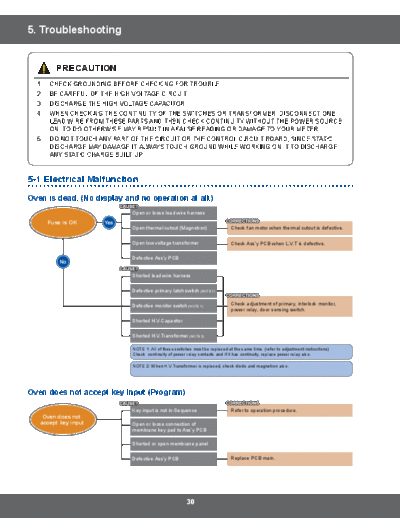
5-1 Electrical Malfunction
Oven is dead. (No display and no operation at all.)
Open or loose lead wire harness
Fuse is OK
Open thermal cutout (Magnetron) Check fan motor when thermal cutout is defective.
Open low voltage transformer Check Ass'y PCB when L.V.T is defective.
Defective Ass'y PCB
Shorted lead wire harness
Defective primary latch switch (NOTE 1)
Defective monitor switch (NOTE 1) Check adjustment of primary, interlock monitor,
power relay, door sensing switch.
Shorted H.V.Capacitor
Shorted H.V.Transformer (NOTE 2)
NOTE 1: All of these switches must be replaced at the same time. (refer to adjustment instructions)
Check continuity of power relay contacts and if it has continuity, replace power relay also.
NOTE 2: When H.V.Transformer is replaced, check diode and magnetron also.
Oven does not accept key input (Program)
Key input is not in-Sequence Refer to operation procedure.
Oven does not
accept key input Open or loose connection of
membrane key pad to Ass'y PCB
Shorted or open membrane panel
Defective Ass'y PCB Replace PCB main.
30
5. Troubleshooting
Timer starts countdown but no microwave oscillation.
(No heat while oven lamp and fan motor turn on.)
Timer starts Off-alignment of latch switches Adjust door and latch switches.
countdown but
no microwave Open or loose connection of high Check high voltage component according to
oscillation voltage circuit especially magnetron component test procedure and replace if it is
filament circuit (NOTE) defective.
Defective high voltage components
H.V.Transformer H.V. Capacitor
H.V.Diode, H.V.Fuse Magnetron
Open or loose wiring of power relay
Defective primary latch switch
Defective power relay or Ass'y PCB Replace PCB main.
NOTE: Large contact resistance will bring lower magnetron filament voltage and cause magnetron
to lower output and/or intermittent oscillation.
Oven can program but timer does not start.(A message of "Close Door" appears on the display.)
Oven can program Open or loose wiring of secondary Adjust door and interlock switches.
but timer does not start interlock switch
(A message of "Close Door"
appears on the display.) Off-alignment of primary interlock
Defective secondary interlock S/W
Microwave output is low. (Oven takes longer time to cook food.)
Decrease in power source voltage Consult electrician.
Microwave
output is low Open or loose wiring of magnetron
filament circuit.
(Intermittent oscillation)
Aging of magnetron
Fan motor turns on when plugged in.
Fan motor turns Tighten door sensing switch wiring.
Loose wiring of door sensing switch
on when plugged in
Oven does not operate and return to the plugged in mode.
Oven does not
operate and return to Defective Ass'y PCB Replace PCB main.
the plugged
in mode
31
5. Troubleshooting
Loud buzzing noise can be heard.
Loose fan and fan motor Tighten screws of fan motor.
Loud buzzing noise
can be heard Loose screws on H.V.Transformer Tighten screws of H.V.Transformer.
Shorted H.V.Diode Replace H.V.Diode.
Turntable motor does not rotate.
Open or loose wiring of Replace turntable motor.
Turntable motor does turntable motor.
not rotate.
Defective turntable motor
Oven stops operation during cooking.
Open or loose wiring of primary Adjust door and latch switches.
Oven stops operation interlock switch
during cooking
Operation of thermal cutout (Magnetron)
Sparks.
Metallic ware or cooking dishes Inform the customer: Do not use any type of
touching on the oven wall cookware with metallic trimming
Sparks
Ceramic ware trimmed with gold or
silver powder also causes sparks
Uneven cooking.
Uneven cooking Uneven intensity of microwave due Aluminum foil should not be placed in the oven.
to its characteristics
Use plastic wrap or cover with a lid.
Stir once or twice while cooking foods such as
soup, cocoa, or milk.
Noise from the turntable motor when it starts to operate.
Noise from the
turntable motor when Noise may result from the motor Replace turntable motor.
it starts to operate.
32
5. Troubleshooting
5-2 Error Code List
Gas Sensor
Error Code Others (E-0X, Letter) Solution
Sensor open error. Check unplugged sensor,
wiring or smart board. If necessary, replace
E-11 OPEN ERROR' of gas sensor.
sensor. If error code appears when starting
sensor function, replace smart board.
Sensor short error.
Check shorted sensor or smart board.
E-12 SHORT ERROR' of gas sensor. If necessary, replace sensor. If error code
appears when starting sensor function,
replace smart board.
Communication Error between Main PCB and Replace Communication Wire or Replace
E-83
Sub PCB. Control Circuit Board.
TE Touch Communication Error (10seconds). Replace Control Circuit Board.
33
5. Troubleshooting
5-2-1 OPEN ERROR of gas sensor/SHORT ERROR of gas sensor
"E-11" or "E-12" is displayed.
Is the Connector CN301 NO Put the connector to
connected to the board properly? proper position.(CN301)
YES
Is the Gas Sensor
NO Connect the gas sensor to
connected to Wire harness-S
properly? wire harness-S properly.
YES
Check gas sensor data value. NO
(Press 'Popcorn' and 'Auto Defrost' at once.) Replace the Main PBA.
Is sensor data value shown
on the display?
YES
Perform the operation again and
check if it is working properly.
34
5. Troubleshooting
5-2-1 Communication Error between Main PCB and Sub PCB
"E-83" is displayed.
Check the connection
between wire harness-C and the board. NO
Connect the wire properly.
Are they connected properly?
YES
Check the connection
NO Connect the both
between wire harness-C and wire harness-D.
Are they connected properly? wire properly.
NO
Check Communication Wire YES
(Wire harness-C and Wire harness-D). Replace the wire.
Are they damaged?
NO
S/W Error
NO After Power > On,
does the symptom continue?
YES
Replace the Main PBA
and Sub module.
Perform the operation again and check if it
is working properly.
35
5. Troubleshooting
5-2-1 Touch Communication Error
"TE" is displayed.
Is the key not recognized YES
at all?
NO
Is the key recognized YES
intermittently?
NO
Is a specific key YES
not recognized?
NO
The membrane
is defective.
S/W Error
Replace the Assy Door-A
(Include switch membrane).
NO After Power > On,
does the symptom continue?
YES
Replace the PCB
(Sub Module).
Perform the operation again and check if it
is working properly.
36
◦ Jabse Service Manual Search 2026 ◦ Jabse Pravopis ◦ onTap.bg ◦ Other service manual resources online : Fixya ◦ eServiceinfo