Service Manuals, User Guides, Schematic Diagrams or docs for : Samsung Microwave SMH1816S_XAA Service Manual 3. Disassembly and Reassembly
<< Back | HomeMost service manuals and schematics are PDF files, so You will need Adobre Acrobat Reader to view : Acrobat Download Some of the files are DjVu format. Readers and resources available here : DjVu Resources
For the compressed files, most common are zip and rar. Please, extract files with Your favorite compression software ( WinZip, WinRAR ... ) before viewing. If a document has multiple parts, You should download all, before extracting.
Good luck. Repair on Your own risk. Make sure You know what You are doing.
Image preview - the first page of the document
>> Download 3. Disassembly and Reassembly documenatation <<
Text preview - extract from the document
3. Disassembly and Reassembly

MAGNETRON, MOTOR ASSEMBLY, VENT BLOWER AND HIGH VOLTAGE TRANSFORMER
Oven must be removed from wall.
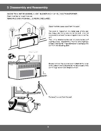
REMOVING OVEN FROM WALL (2 PEOPLE REQUIRED)


                                          Disconnect the power cord from the outlet.

                                          The oven is hooked on the metal tabs of the wall
                                          mounting plate that is secured to the wall. It is not
                                          necessary to remove this mounting plate to service this
                                          unit.
                                          This unit is attached to the cabinet above by two self
                                          aligning screws. Support the unit while removing these
                                          screws allowing it to hinge downward to disengage the
                                          unit from the mounting plate.


                    House Duct


                                          Be aware there may also be a connection to the range
                                          vent ductwork that is attached to the top or back of the
                                          unit through an exhaust adapter/damper.


                                          Remove the oven from the wall


                                      8
3. Disassembly and Reassembly

3-1 Replacement of High Voltage Transformer

         Parts           Explaination Photo               Explaination


                                              1.   Disconnect oven power.

                                              2.   Remove Grille.
Grille
                                                   1) Remove 2 screws
                                                   2) Slide the Grille to the left,
                                                      then pull it straght out.


                                              3.   Remove Panel Outer by
Panel Outer                                        pulling it to the rear of the set.


                                       9
3. Disassembly and Reassembly

3-1 Replacement of High Voltage Transformer

    Parts         Explaination Photo                             Explaination


                                            4.   Discharge the High voltage capacitor.


High voltage
capacitor


                                            5.   Disconnect all the leads.


                                                                                   6.    Remove
Base Bottom                                                                              Base
                                                                                         bottom.


HV Trans                                    7.   Take out the HV Trans.


                                       10
3. Disassembly and Reassembly

3-2 Replacement of Magnetron

       Parts                     Explaination Photo                              Explaination


                                                                 Remove the magnetron including the shield
                                                                 case, permanent magnet, choke coils and
                                                                 capacitors (all of which are contained in one
                                                                 assembly).
                                                                 1. Disconnect all lead wires from the
                                                                     magnetron.


Magnetron


                                                                 2.   Remove nuts (2) securing the magnetron
                                                                      to the wave guide.
                                                                 3.   Take out the magnetron very carefully.


NOTE1: When removing the magnetron, make sure that it antenna does not hit any adjacentparts, or it may be
       damaged.
NOTE2: When replacing the magnetron, be sure to remount the magnetron gasket in the correct position and make
       sure the gasket is in good condition.
NOTE3: Reconnect the lead wire to thermal cutout mounted on the magnetron, before replace the magnetron.


        PRECAUTION
  During replacement, be certain R.F. anode gasket is in place around anode stub.
  PERFORM MICROWAVE LEAKAGE TEST


                                                      11
3. Disassembly and Reassembly

3-3 Replacement of Fan Motor

     Parts           Explaination Photo                         Explaination


                                               1.   Remove Grille and Panel Outer.
                                               2.   Disconnect all lead wires from Fan Motor
                                                    and High Voltage Transformer.


                                               3.   Put out Assy Fan Motor.


Fan Motor


                                               4.   Remove Fan Blade.
                                               5.   Remove screws (2) securing Fan Motor.
                                               6.   Replace Fan Motor to new one.


                                               7.   After replacing Fan Motor and
                                                    reconnecting lead wires, make sure that
                                                    the connectors are connected securely on
                                                    the terminal of Fan Motor by pulling the
                                                    wires lightly.


                                          12
3. Disassembly and Reassembly

3-4 Replacement of Door Assembly
     Parts           Disassembly Photo                                  Explaination


                                              1.   Insert flat screwdriver into the gap between Door
Removal of                                         "A" and Door "C" to remove Door "C". Be careful
Door Assembly                                      when handling Door "C" because it is fragile.Then
                                                   remove the door assembly.


                                              2.   Insert flat screwdriver into the gap between Door
Removal of                                         "A" and Door "C" to remove Door "C".
Door C
◦ Jabse Service Manual Search 2026 ◦ Jabse Pravopis ◦ onTap.bg ◦ Other service manual resources online : Fixya ◦ eServiceinfo