Service Manuals, User Guides, Schematic Diagrams or docs for : Samsung Plasma PS42D5SX chassis D72A D72A-P_Puccini_42D5_chassis_SAMSUNG_PS42D5Sx Disassembly & Reassembly
<< Back | HomeMost service manuals and schematics are PDF files, so You will need Adobre Acrobat Reader to view : Acrobat Download Some of the files are DjVu format. Readers and resources available here : DjVu Resources
For the compressed files, most common are zip and rar. Please, extract files with Your favorite compression software ( WinZip, WinRAR ... ) before viewing. If a document has multiple parts, You should download all, before extracting.
Good luck. Repair on Your own risk. Make sure You know what You are doing.
Image preview - the first page of the document
>> Download Disassembly & Reassembly documenatation <<
Text preview - extract from the document
                                                                                                        Disassembly & Reassembly


12. Disassembly & Reassembly
12-1 Overall Disassembly & Reassembly
   Caution
   - Be sure to separate the power cord before disassembling the unit.
   - Discharge the capacitors first when separating PCB's with high capacity capacitors such as SMPS, X Drive Board, Y Drive
     Board,etc. (Sparks may be generated by an electric charge, and there is a danger of electronic shock.)
   - Check that the cables are properly connected referring to the circuit diagram, when disassembling or assembling the unit and
      take care not to damage the cables.
   - Take care not to damage the Glass Filter at the front.
   - Assemble the boards in the reverse order of the disassembly.


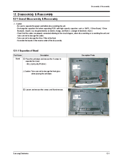
12-1-1 Separation of Stand
Part Name                          Description                                             Description Photo
  Stand      Place the unit down and remove the 4 screws to
             separate the stand.
              : BH,+,S,M4,L35,ZPC(BLK)


              Caution: Take care not to damage the front glass
                       when placing the unit down.


             Loosen and remove the screws and Stand remove.


Samsung Electronics                                                                                                          12-1
Disassembly & Reassembly


12-1-2 Separation of Cable Holder
Part Name                        Description                 Description Photo
             Remove all marked screws
Cable
Holder


             Loosen and remove the screws and Cable Holder
             remove.


12-1-3 Separation of Sub Cover Back
Part Name                        Description                 Description Photo
Sub Cover  Remove all marked screws
  Back


             Loosen and remove the screws and Sub cover
             pull remove.


12-2                                                                        Samsung Electronics
                                                                           Disassembly & Reassembly


12-1-4 Separation of Video Board
Part Name                        Description                   Description Photo
  Video      Separate the cables connected to the Main Board
  Board      remove


             Loosen and remove the 4 screws.


             Separation of Power Button,Ambient Light
            Sensor,IR Receiver PCB.


Samsung Electronics                                                                           12-3
Disassembly & Reassembly


12-1-5 Separation of Back Cover
Part Name                       Description                Description Photo
  Back       Remove all marked screws
  Cover


             Take care not to damage the back cover when
             removing it.


12-1-6 Separation of Function Key
  Part Name                       Description              Description Photo
 Function Key  Remove all marked screws


12-4                                                                       Samsung Electronics
                                                           Disassembly & Reassembly


12-1-7 Separation of Video Board Sub Back
Part Name                        Description    Description Photo
   Video   Remove all marked screws
 Board Sub
   Back


             Remove the Sub Back.


12-1-8 Separation of Power Inlet socket
 Part Name                       Description    Description Photo
 Power Inlet  Loosen and remove the 2 screws.
   socket


Samsung Electronics                                                           12-5
Disassembly & Reassembly


12-1-9 Separation of Main SMPS, DC-DC SMPS
Part Name                       Description                    Description Photo
  Main       Separate the cables connected to the Main SMPS
  SMPS       and then remove the screws.


  DC-DC      Separate the cables connected to the DC-DC SMPS
  SMPS       and then remove the screws.


12-6                                                                           Samsung Electronics
                                                                                Disassembly & Reassembly


12-1-11 Separation of Board
Part Name                        Description                        Description Photo
  Logic      Separate the cables connected to the Logic Board and
  Board      then remove the screws.


 X-Board     Separate the cables connected to the X Drive Board
             and remove the screws.


 Y-Board    Separate the cables connected to the Y Drive Board
            and remove the screws.


 Address    Separate the Y Buffer Board and the Address Buffer
  Buffer    Board depending on the problem
  Board


Samsung Electronics                                                                                12-7
       MEMO


12-8          Samsung Electronics
◦ Jabse Service Manual Search 2026 ◦ Jabse Pravopis ◦ onTap.bg ◦ Other service manual resources online : Fixya ◦ eServiceinfo