Service Manuals, User Guides, Schematic Diagrams or docs for : Samsung Plasma PS42E71SXBWT PS42E71SXBWT Разборка и сборка
<< Back | HomeMost service manuals and schematics are PDF files, so You will need Adobre Acrobat Reader to view : Acrobat Download Some of the files are DjVu format. Readers and resources available here : DjVu Resources
For the compressed files, most common are zip and rar. Please, extract files with Your favorite compression software ( WinZip, WinRAR ... ) before viewing. If a document has multiple parts, You should download all, before extracting.
Good luck. Repair on Your own risk. Make sure You know what You are doing.
Image preview - the first page of the document
>> Download Разборка и сборка documenatation <<
Text preview - extract from the document
                                                                                                       Disassembly & Reassembly


12. Disassembly & Reassembly
12-1 Overhaul Disassembly & Reassembly
   Notice
   - Be sure to separate the power cord before disassembling the unit.
   - Discharge the capacitors first when separating PCB's with high capacity capacitors such as SMPS, X Main Board, Y Main
     Board, etc. (A spark may be generated by the electric charge, and there is danger of electronic shock.)
   - Check that the cables are properly connected referring to the circuit diagram when disassembling or assembling the unit
     taking care not to damage the cables.
   - Take care not to cause a flaw in the Glass Filter in the front.
   - Assemble the boards in the reverse order of the disassembly.
   - The plasma must be layed down on a flat padded surface for disassembly and reassembly.


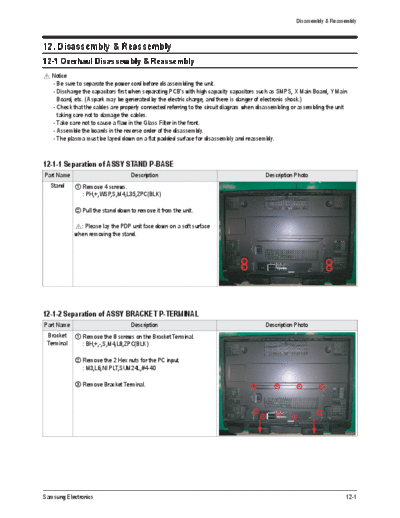
12-1-1 Separation of ASSY STAND P-BASE
Part Name                          Description                                            Description Photo
  Stand      Remove 4 screws.
             : PH,+,WSP,S,M4,L35,ZPC(BLK)

             Pull the stand down to remove it from the unit.

              : Please lay the PDP unit face down on a soft surface
            when removing the stand.


12-1-2 Separation of ASSY BRACKET P-TERMINAL
Part Name                          Description                                            Description Photo
 Bracket     Remove the 8 screws on the Bracket Terminal.
 Terminal    : BH,+,-,S,M4,L8,ZPC(BLK)

             Remove the 2 Hex nuts for the PC input.
             : M3,L6,NI PLT,SUM24L,#4-40

             Remove Bracket Terminal.


Samsung Electronics                                                                                                        12-1
Disassembly & Reassembly


12-1-3 Separation of ASSY COVER P-REAR
Part Name                        Description         Description Photo
  Cover      Remove 22 screws.
  Rear       : BH,+,-,S,M4,L8,ZPC(BLK)

             Remove 4 screws.
            : M8,L16,ZPC(BLK)

             Remove the Cover Rear.


12-1-4 Separation of ASSY PCB MISC-MAIN
Part Name                        Description         Description Photo
  Main       Remove 4 screws
  Board      : PH,+,WWP,M3,L8,NI PLT

             Remove all connectors from the board.

             Remove the Main Board.


12-1-5 Separation of Power Inlet socket
Part Name                        Description         Description Photo
  Power      Remove 3 screws.
   Inlet       : BH,+,S,M4,L8,ZPC(YEL)
  socket       : FH,+,M3,L10,NI PLT,SWRCH18A,FP,-

             Remove the Power Inlet socket.


12-2                                                                 Samsung Electronics
                                                                                     Disassembly & Reassembly


12-1-6 Separation of BRACKET-PCB
Part Name                            Description                         Description Photo
  Bracket      Remove 4 screws.
   PCB         : BH,+,-,S,M4,L8,ZPC(BLK)

               Remove 2 screws.
               : BH,+,B,M4,L8,ZPC(BLK)

               Remove the BRACKET-PCB.


12-1-7 Separation of ASSY BOARD P-FUNCTION
  Part Name                           Description                        Description Photo
 Function Key  Remove 2 screw.
               : BH,+,-,S,M4,L8,ZPC(BLK)

                  Remove the Function Board.


12-1-8 Separation of ASSY BRACKET P-WALL
Part Name                           Description                          Description Photo
  Wall         Remove 8 screws.
 Bracket      : BH,+,B,M4,L12,ZPC(BLK)

               Remove 8 screws.
              : BH,+,S,M4,L10,ZPC(BLK)

               Remove Wall Bracket.

                : Please lay the PDP panel face down on a soft surface
              when separating front cover.


Samsung Electronics                                                                                     12-3
Disassembly & Reassembly


12-1-9 Separation of ASSY SPEAKER P
Part Name                      Description              Description Photo
  Cover      Remove 11 screw.
   Rear      : BH,+,-,S,M4,L8,ZPC(BLK)
  Bottom


 Speaker     Remove 4 screws.
             : BH,+,WP,B,M4.0,L12,ZPC(BLK),SWRCH18A,-

             Remove the Speaker.


12-1-10 Separation of ASSY BOARD P-POWER & IR
Part Name                      Description              Description Photo
  Power  Remove 2 screw.
     &     : BH,+,-,S,M4,L8,ZPC(BLK)
 IR Board
           Remove the Power & IR Board.


12-4                                                                    Samsung Electronics
                                                                                    Disassembly & Reassembly


12-1-11 Separation of ASSY BOARD P-SIDE AV
Part Name                          Description                          Description Photo
 Side AV     Remove 2 screw.
             : BH,+,-,S,M4,L8,ZPC(BLK)

             Remove the Side AV assy.


12-1-12 Separation of ASSY PCB P-SMPS & SMPS DC-DC
Part Name                          Description                          Description Photo
  SMPS       Detach all connectors from the Assy PCB P-SMPS.
    &
  SMPS       Remove 8 screws.
  DC-DC      : PH,+,WWP,M3,L8,NI PLT

             Remove the Assy SMPS PCB.

             Detach all connectors from the Assy SMPS DC/DC
             Board.

             Remove 4 screws.
             : PH,+,WWP,M3,L8,NI PLT

             Remove the SMPS DC/DC Board.

               : Wear gloves when handling the power board as there
            may be some remaining electrical charge in the capacitor.
            Specifically, avoid touching any part of the capacitor.


Samsung Electronics                                                                                    12-5
Disassembly & Reassembly


12-1-13 Separation of ASSY PDP MODULE P-LOGIC MAIN BOARD
Part Name                        Description                    Description Photo
  Logic      Detach all connectors from the Logic Main Board.
  Board
             Remove 4 screws.
             : WSP,PH,+,M3,L8,NI PLT

             Remove the Logic Main Board.


12-6                                                                            Samsung Electronics
12-1-14 Separation of ASSY PDP MODULE P-X MAIN BOARD
Part Name                         Description                       Description Photo
Flat Cable  Detach all Connectors from the X Main Board.

             To separate the Flat Cable of the X-Board, press the
            upper and the lower sides of the connector.


  X-Main     Remove 4 screws.
  Board      : PH,+,WWP,M3,L8,NI PLT

             Remove the X-Main Board.


Samsung Electronics                                                                     12-7
Disassembly & Reassembly


12-1-15 Separation of ASSY PDP MODULE P-Y MAIN BOARD
Part Name                        Description                        Description Photo
Flat Cable  Detach the 4 scan board connectors from the panel by
            pulling the holder from both the top and bottom ends.


  Y-Scan     Remove 2 screws.
             : PH,+,WWP,M3,L8,NI PLT


Connectors  Separate the scan board from the Y-Main Board by
            detaching the 3 connectors and remove the Scan
            Boards.


12-8                                                                                Samsung Electronics
                                                                        Disassembly & Reassembly


Part Name                        Description                Description Photo
  Y-Main     Remove 4 screws.
  Board      : PH,+,WWP,M3,L8,NI PLT

             Detach all connectors from the Y-Main Board.


Samsung Electronics                                                                        12-9
Disassembly & Reassembly


12-1-16 Separation of ASSY PDP MODULE P-ADDRESS BUFFER BOARD
Part Name                           Description                   Description Photo
  Still Bar    Remove 3 screws.
               : PH,+,WWP,M3,L8,NI PLT

               Remove the still bar.


   Buffer      Detach the all connectors from the buffer board.

               Remove 10 screws.
               : PH,+,WWP,M3,L8,NI PLT

               Remove the E-Board and F-Board.


12-10                                                                             Samsung Electronics
◦ Jabse Service Manual Search 2026 ◦ Jabse Pravopis ◦ onTap.bg ◦ Other service manual resources online : Fixya ◦ eServiceinfo