Service Manuals, User Guides, Schematic Diagrams or docs for : Samsung Range Gas NX58H9500WS_AA 4.Disassembly_and_Reassembly
<< Back | HomeMost service manuals and schematics are PDF files, so You will need Adobre Acrobat Reader to view : Acrobat Download Some of the files are DjVu format. Readers and resources available here : DjVu Resources
For the compressed files, most common are zip and rar. Please, extract files with Your favorite compression software ( WinZip, WinRAR ... ) before viewing. If a document has multiple parts, You should download all, before extracting.
Good luck. Repair on Your own risk. Make sure You know what You are doing.
Image preview - the first page of the document
>> Download 4.Disassembly_and_Reassembly documenatation <<
Text preview - extract from the document
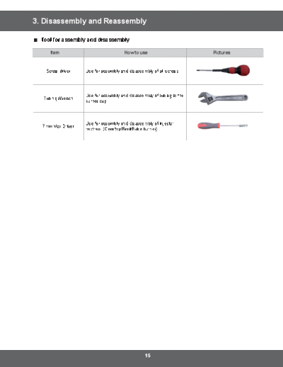
Screw driver Use for assembly and disassembly of all screws
Use for assembly and disassembly of tubing to the
Tubing Wrench
burner cup
7mm Vox Driver
15
3-1 COVER MOTOR CONVECTION
WARNING
WARNING
EXPLOSION, FIRE, AND ASPHYXIATION HAZARD
the range. Replace all panels before operating range. Failure to do so can result in death or personal
CAUTION
When you work on the gas range, be careful when handling sheet metal parts. Sharp edges may be
present, and you can cut yourself if you are not careful.
Explanation Photo Explanation
4 4
4 4
Cover Motor
Convection
4 4
4 4 1. Turn off the electrical supply going to the range.
2. Shut off the gas shut-off valve in the gas supply line to
the range.
3. Pull the range away from the wall so that you can
access the rear panel.
4. Remove 8 screws from Cover Motor Convection and
separate Cover Motor Convection from the range.
16
3-2 ASSY CONTROL BOX
WARNING
WARNING
EXPLOSION, FIRE, AND ASPHYXIATION HAZARD
the range. Replace all panels before operating range. Failure to do so can result in death or personal
CAUTION
When you work on the gas range, be careful when handling sheet metal parts. Sharp edges may be
present, and you can cut yourself if you are not careful.
Explanation Photo Explanation
2 2 2 2
1. Remove 6 Knobs from the Assy Control
Box.
2. Remove 2 screws from the each 5 Holder
Knobs except for Holder Knob Warmer.
2 3 3 3
3. Open the Door and Remove 4 screws
from the bottom of Assy Control Box.
4. Lift the Assy Control Box slightly to
separate from the range. Wire Main
is still connected to the Assy Display of
5. Disconnect 3 wire connectors from the
Disconnect the wire
6. Remove the Assy Control Box from the
Assy Wire A
range.
17
3-3 ASSY FRAME COOKTOP
WARNING
WARNING
EXPLOSION, FIRE, AND ASPHYXIATION HAZARD
the range. Replace all panels before operating range. Failure to do so can result in death or personal
CAUTION
When you work on the gas range, be careful when handling sheet metal parts. Sharp edges may be
present, and you can cut yourself if you are not careful.
Explanation Photo Explanation
Cover Air
1. Turn off the electrical supply going to the
range.
2. Shut off the valve in the gas supply line to
the range.
3. Lift off 3 Grates and a Cover Air.
4. Lift off 5 burner caps and heads from the
burner cups.
5. Remove screws from the each 5 burner
cups and pull out all knob dials.
Assy Grate
6. Remove 2 screws from the rear of the
Frame Cooktop.
7. Push the Burner cups down to the Frame
Cooktop.
Burner Cap
6 6 6 8. Remove the Frame Cooktop.
Burner Head
Burner Cup Make sure the electrodes are placed
under the openings of Cooktop to
prevent interference and damage
Electrode
during replacement.
18
3-4 SIDE PANEL
WARNING
Disconnect power before servicing the range. Replace all panels before operating range. Failure to do so
can result in death or electrical shock.
WARNING
EXPLOSION, FIRE, AND ASPHYXIATION HAZARD
the range. Replace all panels before operating range. Failure to do so can result in death or personal
CAUTION
When you work on the gas range, be careful when handling sheet metal parts. Sharp edges may be
present, and you can cut yourself if you are not careful.
Explanation Photo Explanation
2 2
2 2
1. Follow the steps in 3-1, 3-2, and 3-3.
2. Remove 2 screws from each side of
Assy Burner Box.
RIGHT
3 3
3. Remove 4 screws from each Side Panel.
3 3
4. Remove the Door and open the Drawer.
5. Slightly pull out the Side Panel from the
1 LEFT range.
3 3
2
3 3
19
3-5 ASSY BURNER BOX
WARNING
Disconnect power before servicing the range. Replace all panels before operating range. Failure to do so
can result in death or electrical shock.
WARNING
EXPLOSION, FIRE, AND ASPHYXIATION HAZARD
the range. Replace all panels before operating range. Failure to do so can result in death or personal
CAUTION
When you work on the gas range, be careful when handling sheet metal parts. Sharp edges may be
present, and you can cut yourself if you are not careful.
Explanation
1. Follow the steps in 3-1, 3-2, and 3-3.
3. Remove the Assy tube-manifold using a tubing wrench.
4. Remove 1 screw from a Cover Rear and 6 screws from a Assy Burner Box.
5. Remove 1 ground screw and Disconnect wires connected to a Cover Rear.
6. Remove the Assy Burner Box.
20
Explanation Photo
Guide Cooktop Rear
2 2
2
4
Assy Tube Manifold
3
4 4
4
4
Ground screw
5
4 4
Burner Box
21
3-6 PCB ASSEMBLY, ASSY-FRAME COOKTOP
WARNING
Disconnect power before servicing the range. Replace all panels before operating range. Failure to do so
can result in death or electrical shock.
WARNING
EXPLOSION, FIRE, AND ASPHYXIATION HAZARD
the range. Replace all panels before operating range. Failure to do so can result in death or personal
CAUTION
When you work on the gas range, be careful when handling sheet metal parts. Sharp edges may be
present, and you can cut yourself if you are not careful.
Parts Explanation Explanation Photo
1. Follow the step on 3-1. 3 3
2. Disconnect 10 wire connectors
PCB
from the Main PCB.
ASSEMBLY
3. Remove 2 screws of PCB
assembly and replace the PCB.
2
1. Follow the steps on 3-1.
ASSY- 2. Disconnect 7 wire connectors
FRAME from the Spark Module.
2
COOKTOP 3. Remove 2 screws from the Spark
Module and replace it.
22
3-7 ASSY DISPLAY, ROTARY SWITCH
Parts Explanation Explanation Photo
Warming Drawer
1. Follow the steps on 3-2.
2. Bend the Tail Holder of the Assy
ASSY 3 3
DISPLAY 3. Remove 2 screws from the Assy
Display.
4. Replace the Assy Display. 2
Warming Drawer Warming Drawer
Warming Drawer
1. Follow the steps in 3-1 and 3-2.
2. Remove 2 screws from the Holder
ROTARY
Knob Warmer. 2
SWITCH
3. Pull out the Rotary Switch and
replace it.
23
3-7 ASSY DISPLAY, ROTARY SWITCH
WARNING
Disconnect power before servicing the range. Replace all panels before operating range. Failure to do so
can result in death or electrical shock.
WARNING
EXPLOSION, FIRE, AND ASPHYXIATION HAZARD
the range. Replace all panels before operating range. Failure to do so can result in death or personal
CAUTION
When you work on the gas range, be careful when handling sheet metal parts. Sharp edges may be
present, and you can cut yourself if you are not careful.
CAUTION
24
3-8 ELECTRODE
Parts Explanation Explanation Photo
Gas Burner Cup Tube
1. Follow the steps on 3-1 and 3-3.
2. Disconnect the wire connectors
from the terminal on the Spark
module.
3. To remove the Electrode from
ELECTRODE the cup, squeeze the two outside
edges of the clip under the
electrode together while pulling
to remove the locking clip. Slide Bracket Spring Electrode
the electrode and the wire from Electrode
the cup. In case of Dual Burner, Holder & Spring ETC
Rotate Electrode and pull it up.
Wire Housing
25
3-8 ELECTRODE
WARNING
WARNING
EXPLOSION, FIRE, AND ASPHYXIATION HAZARD
the range. Replace all panels before operating range. Failure to do so can result in death or personal
CAUTION
When you work on the gas range, be careful when handling sheet metal parts. Sharp edges may be
present, and you can cut yourself if you are not careful.
CAUTION
26
3-9 BURNER CUP
Parts Explanation Explanation Photo
1. Follow the steps on 3-1 and 3-3. Burner Cup Tube
2. Using a tubing wrench on the
lock wrench on the burner cup
in place while disconnecting the
gas line.
BURNER 3. Remove
CUP
4. The burner cup can be
removed. Replace it.
The new burner cup must be
Bracket Spring Electrode
replaced with the same size
as the one removed. Electrode
5. After replacement, You must
check gas leakage
Wire Housing
27
3-9 BURNER CUP
WARNING
Disconnect power before servicing the range. Replace all panels before operating range. Failure to do so
can result in death or electrical shock.
WARNING
EXPLOSION, FIRE, AND ASPHYXIATION HAZARD
the range. Replace all panels before operating range. Failure to do so can result in death or personal
CAUTION
When you work on the gas range, be careful when handling sheet metal parts. Sharp edges may be
present, and you can cut yourself if you are not careful.
CAUTION
28
3-10 GAS ORIFICE NOZZLE
Parts Explanation Explanation Photo
1 1
1
1
1
1. To
the burner cup in a vise and
remove the with a 9/32-
GAS inch socket wrench.
ORIFICE In case of the Dual Burner, it
NOZZLE
2. Install
burner cup.
Gas Burner Tube
Nozzle Cup
29
3-11 VALVE COOKTOP
WARNING
WARNING
EXPLOSION, FIRE, AND ASPHYXIATION HAZARD
the range. Replace all panels before operating range. Failure to do so can result in death or personal
CAUTION
When you work on the gas range, be careful when handling sheet metal parts. Sharp edges may be
present, and you can cut yourself if you are not careful.
CAUTION
Check the parts code of the knob and/or Switch Ignition in case of replacement.
30
3-11 VALVE COOKTOP
Parts Explanation Explanation Photo
Switch Ignition
1. Follow the steps 3-2 and 3-3.
2. Open or remove a Door.
3. Place
of the switch ignition and pull it
straight out to release it from
the control shaft.
4. Using a tubing wrench and
a channel lock wrench,
disconnect the gas lines from
the valve cooktop. Do not
VALVE bend or crimp gas lines during
COOKTOP Removal.
Adaptor
5. Remove the Valve Cooktop
followed by removal of 1 screw
on the valve cooktop.
6. Replace the Valve Cooktop and
Check gas leakage.
5
When assembling or
disassembling the valve,
the screw torque should be
31
3-11 VALVE COOKTOP
WARNING
Disconnect power before servicing the range. Replace all panels before operating range. Failure to do so
can result in death or electrical shock.
WARNING
EXPLOSION, FIRE, AND ASPHYXIATION HAZARD
the range. Replace all panels before operating range. Failure to do so can result in death or personal
CAUTION
When you work on the gas range, be careful when handling sheet metal parts. Sharp edges may be
present, and you can cut yourself if you are not careful.
CAUTION
Check the parts code of the knob and/or Switch Ignition in case of replacement.
32
3-12 SWITCH IGNITION
Parts Explanation Explanation Photo
Switch Ignition
1. Follow the steps on 3-1, 3-2,
and 3-3. 2 2 2 2 2
2. Place
of the switch ignition and pull
it straight out to release it from
SWITCH the control shaft. Repeat this
IGNITION step to all switches.
3. Disconnect the wires from the
connectors on the Cover Rear.
4. Bend the Clamp to disconnect Connector of
the Switch Ignition Wire. Switch Ignition
5. Replace the Switch Ignition.
33
3-12 SWITCH IGNITION
WARNING
Disconnect power before servicing the range. Replace all panels before operating range.
Failure to do so can result in death or electrical shock.
WARNING
EXPLOSION, FIRE, AND ASPHYXIATION HAZARD
the range. Replace all panels before operating range. Failure to do so can result in death or personal
CAUTION
When you work on the gas range, be careful when handling sheet metal parts. Sharp edges may be
present, and you can cut yourself if you are not careful.
CAUTION
Check the parts code of the knob and/or Switch Ignition in case of replacement.
34
3-13 ASSY MOTOR , TCO
Parts Explanation Explanation Photo
2 2
Hooks of Bracket Motor Rear
1. Follow the steps on 3-1 and 3-3.
2. Remove 2 screws from the
Guide Cooktop Rear and a
Bracket Motor Front.
3. Disconnect 2 terminal housings
from the Assy Motor and the 2 2
ASSY TCO. 3
MOTOR and 4. Remove the Assy Motor and 3
TCO unbend the hook of the Bracket
Motor Rear. Housing
7
5. Remove 2 screws from the
Bracket Motor Front and the
Bracket Motor Rear.
6. Remove 2 screws from the
TCO, then replace the TCO.
5 5
5
35
3-13 ASSY MOTOR , TCO
WARNING
Disconnect power before servicing the range. Replace all panels before operating range. Failure to do so
can result in death or electrical shock.
WARNING
EXPLOSION, FIRE, AND ASPHYXIATION HAZARD
the range. Replace all panels before operating range. Failure to do so can result in death or personal
CAUTION
When you work on the gas range, be careful when handling sheet metal parts. Sharp edges may be
present, and you can cut yourself if you are not careful.
36
3-14 ASSY DOOR LATCH
Parts Explanation Explanation Photo
Bracket-Latch Rear
Cavity Front
3 3
1. Follow steps on 3-5.
2 2
2. Remove 2 screws from the
Cavity Front.
3. Remove 2 screws from the
Bracket-Latch sub to the rear of
the range.
Bracket-Latch Rear
4. Disconnect wires from the door
ASSY latch to the rear of the range
4 4
DOOR and remove it.
LATCH 5. Remove 2 screws holding the
Assy bracket-latch rear to the
rear of the range.
6. Replace the Assy Bracket
Latch.
7. Test the Assy Door Latch to
make sure it is latching and
unlatching properly.
Assy Bracket Latch
37
3-14 ASSY DOOR LATCH
WARNING
Disconnect power before servicing the range. Replace all panels before operating range. Failure to do so
can result in death or electrical shock.
WARNING
EXPLOSION, FIRE, AND ASPHYXIATION HAZARD
the range. Replace all panels before operating range. Failure to do so can result in death or personal
CAUTION
When you work on the gas range, be careful when handling sheet metal parts. Sharp edges may be
present, and you can cut yourself if you are not careful.
38
3-15 ASSY PROBE
Parts Explanation Explanation Photo
Connector of
Assy Probe
3
Assy Probe
1. Follow steps on 3-4.
2
2. To replace the Assy Probe, 2
ASSY remove 2 screws from the Assy
PROBE Probe.
3. Disconnect the Assy Probe
connector.
4. Replace the Assy Probe.
39
3-16 SWITCH-DOOR PLUNGER
WARNING
Disconnect power before servicing the range. Replace all panels before operating range. Failure to do so
can result in death or electrical shock.
WARNING
EXPLOSION, FIRE, AND ASPHYXIATION HAZARD
the range. Replace all panels before operating range. Failure to do so can result in death or personal
CAUTION
When you work on the gas range, be careful when handling sheet metal parts. Sharp edges may be
present, and you can cut yourself if you are not careful.
Parts Explanation Explanation Photo
1. Turn off the electrical supply
going to the range.
Switch Door
2. Shut off the gas shut-off valve in
Plunger
the gas supply line to the range.
3. Open the oven door.
4. Carefully pull out the switch
door plunger switch from the
upper right corner of the cavity
SWITCH- front. Gently grasp the plunger
DOOR with pliers and work from side
PLUNGER to side while pulling. Pull out far
enough to expose the wires.
5. Note the location and mark the
wires; then disconnect the wire
to the switch door plunger.
6. Replace with the switch-door
plunger, reconnect the wires
in their original positions, and
reinstall switch in the oven
frame.
40
3-17 ASSY LAMP
WARNING
Disconnect power before servicing the range. Replace all panels before operating range. Failure to do so
can result in death or electrical shock.
WARNING
EXPLOSION, FIRE, AND ASPHYXIATION HAZARD
the range. Replace all panels before operating range. Failure to do so can result in death or personal
CAUTION
When you work on the gas range, be careful when handling sheet metal parts. Sharp edges may be
present, and you can cut yourself if you are not careful.
Parts Explanation Explanation Photo
1. Open the oven door and
remove the racks from inside
the oven.
2. The oven lamp is in the upper
right-hand corner of the oven
ASSY LAMP cavity. Turn oven lamp cover
counterclockwise to loosen and
remove the cover.
3. Remove the oven light bulb.
4. After replacement, Install Oven
light cover by turning clockwise.
41
3-18 SENSOR-THERMISTER
WARNING
Disconnect power before servicing the range. Replace all panels before operating range. Failure to do so
can result in death or electrical shock.
WARNING
EXPLOSION, FIRE, AND ASPHYXIATION HAZARD
the range. Replace all panels before operating range. Failure to do so can result in death or personal
CAUTION
When you work on the gas range, be careful when handling sheet metal parts. Sharp edges may be
present, and you can cut yourself if you are not careful.
Parts Explanation Explanation Photo
1. Follow steps on 3-1..
2. Open the oven door and
remove the racks from inside
the oven.
4 4
3. Disconnect connector of the
sensor thermistor to the rear of
the range.
4. The oven sensor thermistor is
in the upper left-hand corner
of the oven cavity. Remove
Sensor- 2 screws and carefully pull the
Thermister sensor wire leads until the wire
connectors appear.
5. Reverse the order to install the
Connector
oven temperature sensor.
If you can't access the wire
connectors from inside the
oven, remove the rear cover
panel. Mark and disconnect
the two wiresgoing to the oven
sensor thermistor.
42
3-19 GASKET-DOOR
Parts Explanation Explanation Photo
1. Open the oven door to its fully
down position.
2. Pull the ends of the gasket out
of the liner holes.
3. Pull the oven door gasket clips
out of the holes until all of the
clips are removed.
4. When the service is complete,
Insert gasket clips in each
mounting hole. Push the ends
GASKET of gasket in end holes in the
DOOR bottom of the front oven frame.
5. Close the oven door.
When you install the new
gasket, make sure that all of
the clips are seated in their liner
holes, and that the ends of the
gasket are pushed fully into
their holes. Use the pointed
end of a pencil to push the
gasket ends into the holes.
43
3-20 OVEN DOOR
WARNING
WARNING
CAUTION
When you work on the gas range, be careful when handling sheet metal parts. Sharp edges may be
present, and you can cut yourself if you are not careful
Parts Explanation Explanation Photo
1. Fully open the door.
2. Pull the hinge locks downward.
3. Firmly grasp both side of the
OVEN DOOR door at the top.
4. Close door to the door
removal position, which is
approximately 5 degrees. Lift
door up and out until the hinge
arm are clear of the slot.
44
Parts Explanation Explanation Photo
1. Firmly grasp both sides of the
door at the top position.
2. Fully open the door.
OVEN DOOR
it means that the indentation
is not seated correctly in the
bottom edge of the slot. Push
the hinge locks up to the locked
3. Close the oven door.
45
3-21 HANDLE-DOOR, GLASS-INNER
Parts Explanation Explanation Photo
1. Remove the oven door from the
range.
2. Place the oven door on a
padded work surface with the
front glass facing down. 3 3 3
3. Remove 3 bottom screws from 4 4
the door.
4. Remove 2 Handle-screws from
the door.
HANDLE-
DOOR ,
GLASS-
INNER
5. Lift the door rear assembly off
the front assembly and set it
aside
6. Remove 2 spacers and
2 screws.
46
3-21 HANDLE-DOOR, GLASS-INNER
Parts Explanation Explanation Photo
To
1. Remove 2 screws to remove
Handle- Door.
NX58H9500WS NX58H9950WS
To
1. Remove 6screws from rear side
HANDLE- of door to remove 2 Hinge-Door.
DOOR ,
GLASS- 2. Remove 4screws to remove
INNER Glass- Inner Sub Assembly.
3. Remove 7screws to remove
.
4. Remove
out the Glass-Inner assembly.
5. Unfold
Frame Inner Glass to take out
Glass-Inner
47
3-22 ASSY POWER CORD
WARNING
WARNING
EXPLOSION, FIRE, AND ASPHYXIATION HAZARD
the range. Replace all panels before operating range. Failure to do so can result in death or personal
CAUTION
When you work on the gas range, be careful when handling sheet metal parts. Sharp edges may be
present, and you can cut yourself if you are not careful.
Parts Explanation Explanation Photo
Cover
1. Turn off the electrical supply
going to the range.
2. Remove the cover screw and
ASSY pull it out from the range.
POWER
3. Remove the ground wire screw.
CORD Ground Wire Housing
4. Pull on the power cord wire.
5. Disconnect the housing of the
wire and replace it.
48
3-23 BURNER BROIL
WARNING
WARNING
EXPLOSION, FIRE, AND ASPHYXIATION HAZARD
the range. Replace all panels before operating range. Failure to do so can result in death or personal
CAUTION
When you work on the gas range, be careful when handling sheet metal parts. Sharp edges may be
present, and you can cut yourself if you are not careful.
Parts Explanation Explanation Photo
Bracket HSI
1. Follow the step on 3-1.
Connector Wire
2. Open the oven door and remove
the racks from inside the oven.
3. Disconnect the wires or the
connector of the HSI.
and mark the two wires going to
4
4. Remove 1 screw of bracket HSI-
wire.
5 5
5. Remove 4 screws on bracket-
broil spreader to top of oven. 5 5
BURNER 6. Support the burner-broil with
BROIL one hand, remove 2 screw
supporting the burner-broil to the
front and the rear of the oven.
7. Pull the upper ASSY-BURNER 6
BROIL SPREADER to Flame Guide
disconnect it from the holder
nozzle-broil on the rear wall of
the oven.
8. Carefully remove ASSY-
BURNER BROIL SPREADER. 6 Bracket Broil
9. Separate the burner broil and Spreader
bracket-broil spreader.
10. Replace the Burner Broil.
Burner Broil
49
3-24 HOT SURFACE IGNITOR, NOZZLE BROIL BURNER, HOLDER BROIL-
BURNER
WARNING
Disconnect power before servicing the range. Replace all panels before operating range. Failure to
WARNING
EXPLOSION, FIRE, AND ASPHYXIATION HAZARD
the range. Replace all panels before operating range. Failure to do so can result in death or personal
CAUTION
When you work on the gas range, be careful when handling sheet metal parts. Sharp edges may be
present, and you can cut yourself if you are not careful.
Parts Explanation Explanation Photo
12. To replace the HSI of the
burner broil, remove 2 screws
assembled to HSI
12
13. To replace the nozzle broil-
HOT
burner, remove the gas nozzle
SURFACE
with a 9/32-inch socket wrench. 14 Remove the gas
IGNITOR
14. To remove the holder-broil nozzle
BURNER burner, remove 2 screws
BROIL, supporting the holder-broil 14
burner to the rear of the oven.
NOZZLE 15. When the service is complete,
BROIL- reverse the order to install
BURNER, burner broil, HSI, Nozzle and NOTE.
HOLDER Holder broil burner.
BROIL-
BURNER
The
locking screw and opening or
closing the air shutter at the
base of the oven burner. Locking Screw Locking Screw
50
3-25 BURNER BAKE
WARNING
Disconnect power before servicing the range. Replace all panels before operating range. Failure to do so
can result in death or electrical shock.
WARNING
EXPLOSION, FIRE, AND ASPHYXIATION HAZARD
the range. Replace all panels before operating range. Failure to do so can result in death or personal
CAUTION
When you work on the gas range, be careful when handling sheet metal parts. Sharp edges may be
present, and you can cut yourself if you are not careful.
Parts Explanation Explanation Photo
1. Turn off the electrical supply
going to the range.
2. Shut off the gas shut-off valve in
the gas supply line to the range.
3. Open the oven door and remove
the racks from inside the oven.
4. Pull on the wires or the connector
until the wire connector appears Connector
from the back wall of the warming
drawer opening.
5. Disconnect the connector of HSI 6 6 9
of the burner bake.
BURNER
BAKE 6. Remove 2 screws from the back
Lift back to Cavity Floor 9
clear the front edge and lift out
7. Remove 2 screws from the front
of the bracket bake-spreader. Burner Bake
8. Lift front the bracket bake- Bracket Bake
spreader and lift out the bracket- Spreader
bake spreader. HSI
7 7
Surface
9. Remove 2 screws from the
Burner Bake and lift up the burner
bake from the holder-bake burner
on the bottom of the drawer.
51
3-26 HOT SURFACE IGNITOR, NOZZLE BAKE BURNER, HOLDER BAKE-
BURNER
WARNING
Disconnect power before servicing the range. Replace all panels before operating range. Failure to do so
can result in death or electrical shock.
WARNING
EXPLOSION, FIRE, AND ASPHYXIATION HAZARD
the range. Replace all panels before operating range. Failure to do so can result in death or personal
CAUTION
When you work on the gas range, be careful when handling sheet metal parts. Sharp edges may be
present, and you can cut yourself if you are not careful.
Parts Explanation Explanation Photo
HSI
10. To replace the HSI of the
burner bake, remove 2 screws
10
assembled to HSI.
11. To replace the nozzle bake-
12
with a 9/32-inch socket wrench. Nozzle
HOT SURFACE
12. To remove the holder-bake Holder
of the BURNER burner, remove 2 screws
BAKE supporting the holder-bake
12
burner to the rear of the oven.
NOZZLE BAKE- 13. When the service is complete,
BURNER, reverse the order to install
HOLDER BAKE- Burner bake, HSI, Nozzle,
BURNER Holder bake-burner. NOTE.
The
locking screw and opening or
closing the air shutter at the
base of the oven burner.
Locking Screw Locking Screw
52
3-27 WARMING DRAWER
WARNING
Disconnect power before servicing the range. Replace all panels before operating range. Failure to do so
can result in death or electrical shock.
WARNING
EXPLOSION, FIRE, AND ASPHYXIATION HAZARD
the range. Replace all panels before operating range. Failure to do so can result in death or personal
CAUTION
When you work on the gas range, be careful when handling sheet metal parts. Sharp edges may be
present, and you can cut yourself if you are not careful.
Parts Explanation Explanation Photo
1. Turn off the electrical supply
going to the range.
2. Shut off the gas shut-off valve in
the gas supply line to the range.
3. Open the warming drawer to the
fully opened position.
4. Locate glide lever on each side
WARMING of drawer. Push down on the left
DRAWER glide lever and pull up on the
right glide lever while pulling the
drawer the rest of the way out.
5. Place the ends of the drawer
side rails into the ends of the
drawer glide rails. Push in the
drawer to close the drawer and Drawer Drawer
snap the glide lever into place. Side Rail Side Rail
53
3-28 HEATER WARMING DRAWER
WARNING
Disconnect power before servicing the range. Replace all panels before operating range. Failure to do so
can result in death or electrical shock.
WARNING
EXPLOSION, FIRE, AND ASPHYXIATION HAZARD
the range. Replace all panels before operating range. Failure to do so can result in death or personal
CAUTION
When you work on the gas range, be careful when handling sheet metal parts. Sharp edges may be
present, and you can cut yourself if you are not careful.
Parts Explanation Explanation Photo
Connector of the
heater-warming
1. Turn off the electrical supply drawer
going to the range.
2. Shut off the gas shut-off valve in
the gas supply line to the range.
3. Remove the warming drawer.
4. Disconnect the connector from
HEATER the back wall of the warming
WARMING drawer opening.
DRAWER 5. Remove the bottom screw and
the heater-warming drawer from
the back wall of the warming
drawer opening.
6. Reverse the order to install
and connect the new heater
warming drawer.
5
54
3-29 MOTOR CONVECTION
WARNING
Disconnect power before servicing the range. Replace all panels before operating range. Failure to do so
can result in death or electrical shock.
WARNING
EXPLOSION, FIRE, AND ASPHYXIATION HAZARD
the range. Replace all panels before operating range. Failure to do so can result in death or personal
CAUTION
When you work on the gas range, be careful when handling sheet metal parts. Sharp edges may be
present, and you can cut yourself if you are not careful.
Parts Explanation Explanation Photo
1. Follow the step on 3-1. 4
2. Note, mark, and disconnect wires or
connector going to the motor convection
3. Open the oven door and remove the
racks from inside the oven.
4. Remove 2 screws and the interior cover
casing from the back wall of the oven Connector 4
cavity.
5. Remove the fan nut, fan blade from the
motor convection shaft.
convection nut has clockwise Fan
MOTOR
CONVECTION 6. Unbend the bracket of the back main to
the rear of the range.
7. Pull the motor convection straight out
while rotating the motor convection
Unbend
counterclockwise. Fan Nut the
8. When the service is complete, reverse bracket
the order to install the motor convection.
The
screw and opening or closing the
air shutter at the base of the oven
burner.
55
3-30 HEATER CONVECTION
WARNING
Disconnect power before servicing the range. Replace all panels before operating range. Failure to do so
can result in death or electrical shock.
WARNING
EXPLOSION, FIRE, AND ASPHYXIATION HAZARD
the range. Replace all panels before operating range. Failure to do so can result in death or personal
CAUTION
When you work on the gas range, be careful when handling sheet metal parts. Sharp edges may be
present, and you can cut yourself if you are not careful.
Parts Explanation Explanation Photo
Connector of the
Heater Convection
1. Follow the step on 3-1.
2. To remove heater convection,
disconnect wires or connector going to
the heater-convection
3. Remove 2 screws supporting the
heater-convection to the rear of the
HEATER oven.
CONVECTION
4. Remove 1 screw holding the bracket-
convection heater of the rear of the
oven.
5. Pull out the heater convection.
6. Reverse the order to install the heater 3
convection. 4
Bracket Convection
Heater
56
3-31 BRACKET CAVITY
WARNING
Disconnect power before servicing the range. Replace all panels before operating range. Failure to do so
can result in death or electrical shock.
WARNING
EXPLOSION, FIRE, AND ASPHYXIATION HAZARD
the range. Replace all panels before operating range. Failure to do so can result in death or personal
CAUTION
When you work on the gas range, be careful when handling sheet metal parts. Sharp edges may be
present, and you can cut yourself if you are not careful.
Parts Explanation Explanation Photo
Bracket Cavity
1. Turn off the electrical supply going to
the range.
2. Shut off the gas shut-off valve in the gas
supply line to the range.
Bracket Cavity
3. Open the oven door and remove the
gliding racks from inside the oven.
4. Remove 4 screws from the Bracket
cavity located in the both sides of rear
cavity. 4
4
4 4
57
3-32 ASSY VALVE SAFETY
WARNING
Disconnect power before servicing the range. Replace all panels before operating range. Failure to do so
can result in death or electrical shock.
WARNING
EXPLOSION, FIRE, AND ASPHYXIATION HAZARD
the range. Replace all panels before operating range. Failure to do so can result in death or personal
CAUTION
When you work on the gas range, be careful when handling sheet metal parts. Sharp edges may be
present, and you can cut yourself if you are not careful.
Parts Explanation Explanation Photo
1. Turn off the electrical supply going to
the range. ASSY VALVE SAFETY
2. Shut off the gas shut-off valve in the gas 5
supply line to the range. 45 7
3. Remove the regulator support bracket
from the rear of the range.
4. Carefully identify and mark the wires
going to the ASSY VALVE SAFETY. 5
Disconnect the 4 wires.
7
Cross-wiring the wires to the
ASSY VALVE SAFETY creates an
ASSY VALVE
explosion hazard that can result
SAFETY
property and product damage. Wire
5. Using a tubing wrench and a channel-
lock wrench, disconnect the 3 gas lines 4
from the ASSY VALVE SAFETY. Do not
bend or crimp gas lines during removal.
6.
VALVE SAFETY.
7. Remove 4 screws and the ASSY VALVE
4
SAFETY from the back wall of the
warming drawer opening.
58
3-32 ASSY VALVE SAFETY
WARNING
WARNING
EXPLOSION, FIRE, AND ASPHYXIATION HAZARD
the range. Replace all panels before operating range. Failure to do so can result in death or personal
CAUTION
When you work on the gas range, be careful when handling sheet metal parts. Sharp edges may be
present, and you can cut yourself if you are not careful.
Parts Explanation Explanation Photo
8. Install the new ASSY VALVE SAFETY
from the back wall of the warming
Support Regulator
drawer with 4 screws.
9. Reconnect gas lines to the ASSY
VALVE SAFETY. 8
ASSY VALVE leaks before operation. 8
SAFETY
Cross-wiring the wires to the gas
control valve creates an explosion
8
hazard that can result in death,
product damage.
Rear
10. Reconnect wire connectors in their
original positions.
59
3-33 COVER MOTOR
WARNING
Disconnect power before servicing the range. Replace all panels before operating range. Failure to do so
can result in death or electrical shock.
WARNING
EXPLOSION, FIRE, AND ASPHYXIATION HAZARD
the range. Replace all panels before operating range. Failure to do so can result in death or personal
CAUTION
When you work on the gas range, be careful when handling sheet metal parts. Sharp edges may be
present, and you can cut yourself if you are not careful.
CAUTION
Check the parts code of the knob and/or Switch Ignition in case of replacement.
Parts Explanation Explanation Photo
2
1. Follow the Step A and C.
2. Pull out all Wires on the Cover Motor.
ASSY VALVE
SAFETY 3. Remove 3 screws on the Cover
Motor.
4. Replace the Cover Motor. 3
3
3
60
◦ Jabse Service Manual Search 2026 ◦ Jabse Pravopis ◦ onTap.bg ◦ Other service manual resources online : Fixya ◦ eServiceinfo