Service Manuals, User Guides, Schematic Diagrams or docs for : Samsung Refridgerators RS25H5111SR_AA Service Manual SSEDA-14-RS25H51-131221_PCB_DIAGRAM
<< Back | HomeMost service manuals and schematics are PDF files, so You will need Adobre Acrobat Reader to view : Acrobat Download Some of the files are DjVu format. Readers and resources available here : DjVu Resources
For the compressed files, most common are zip and rar. Please, extract files with Your favorite compression software ( WinZip, WinRAR ... ) before viewing. If a document has multiple parts, You should download all, before extracting.
Good luck. Repair on Your own risk. Make sure You know what You are doing.
Image preview - the first page of the document
>> Download SSEDA-14-RS25H51-131221_PCB_DIAGRAM documenatation <<
Text preview - extract from the document
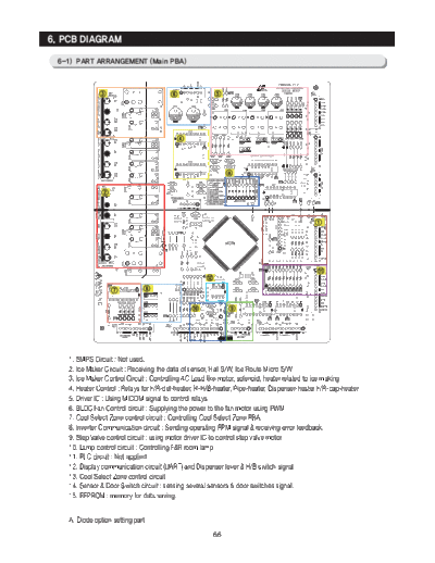
6. PCB DIAGRAM

 6-1) PART ARRANGEMENT (Main PBA)


    1. SMPS Circuit : Not used.
    2. Ice Maker Circuit : Receiving the data of sensor, Hall S/W, Ice Route Micro S/W
    3. Ice Maker Control Circuit : Controlling AC Load like motor, solenoid, heater related to ice making
    4. Heater Control : Relays for F/R-def-heater, R-H/B-heater, Pipe-heater, Dispenser-heater F/R-cap-heater
    5. Driver IC : Using MICOM signal to control relays.
    6. BLDC Fan Control circuit : Supplying the power to the fan motor using PWM
    7. Cool Select Zone control circuit : Controlling Cool Select Zone PBA.
    8. Inverter Communication circuit : Sending operating RPM signal & receiving error feedback.
    9. Step Valve control circuit : using motor driver IC to control step valve motor
    10. Lamp control circuit : Controlling F&R room lamp
    11. PLC circuit : Not applied
    12. Display communication circuit (UART) and Dispenser lever & H/B switch signal
    13. Cool Select Zone control circuit
    14. Sensor & Door Switch circuit : sensing several sensors & door switches signal.
    15. EEPROM : memory for data saving.


    A. Diode option setting part
                                                        66
PCB DIAGRAM

6-2) Connector Layout & Descriptions of Inverter Controller Board


   1. PCB Power Supply : From the SMPS circuit, it supplies 15V and 5V for the Main PBA control and supplies15V and
     5V to the Inverter circuit for the Compressor control.
   2. Inverter Control Circuit : Fridge Compressor Control Circuit.
   3. COMP Driving / Feedback CircuitIt receives the COMP operation signals from the Main PBA and feedbacks the
     inverter errors to the Main PBA.
   4. BOOTSTRAP Charger : It is an independent power circuit for the driving of the IMP High-Phase IGBT.
   5. Current Pickup Circuit : It pickups the currents taken by the Shunt resistance and does the PWM DUTY control.
   6. IPM (FNE41060)
   7. Micom (MN103SFC2D)


                                                        67
PCB DIAGRAM

 6-3) CONNECTOR ARRANGEMENT (Main Board)


                                       68
PCB DIAGRAM


 6-4) Connector Layout & Description (Inverter comp control Board)


 Used for Inverter Model


                                               69
◦ Jabse Service Manual Search 2026 ◦ Jabse Pravopis ◦ onTap.bg ◦ Other service manual resources online : Fixya ◦ eServiceinfo