Service Manuals, User Guides, Schematic Diagrams or docs for : Samsung TV KSBE chassis Desensamble & Reensamble
<< Back | HomeMost service manuals and schematics are PDF files, so You will need Adobre Acrobat Reader to view : Acrobat Download Some of the files are DjVu format. Readers and resources available here : DjVu Resources
For the compressed files, most common are zip and rar. Please, extract files with Your favorite compression software ( WinZip, WinRAR ... ) before viewing. If a document has multiple parts, You should download all, before extracting.
Good luck. Repair on Your own risk. Make sure You know what You are doing.
Image preview - the first page of the document

>> Download Desensamble & Reensamble documenatation <<
Text preview - extract from the document
                                                                            Disassembly & Reassembly


3. Disassembly&Reassembly
3-1 OverallDisassembly&Reassembly
3-1-1 DisassemblingtheCabinet
Part Name                  Description                  Description Photo
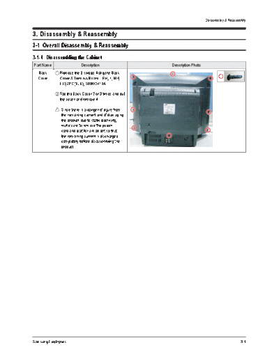
   Back      Remove the 9 screws fixing the Back
   Cover     Cover & Terminal Board. : RH, +, M4,
             L15,ZPC(BLK), SWRCH18A

             Tap the Back Cover 2 or 3 times and pull
             the cover and remove it.

               Since there is a danger of injury from
               the remaining current and of damaging
               the product due to static electricity,
               make sure to remove the power
               cord and wait for a moment so that
               the remaining current is discharged
               completely before disassembling the
               product.


Samsung Electronics                                                                             3-1
Disassembly & Reassembly


3-1-2 DisassemblingtheCRTandChassis
 Part Name                       Description                             Description Photo
  Chassis     Separate the Ass'y Holder chassis from
  Holder      the Front Cabinet.

              Pull the Holder Chassis while pushing
              the catch up.

                you pull it with excessive power, it may
               If
               cause damage to the catch or connector.
               Therefore, pull it until the catch is out of                   Pull the chassis while pushing the
                                                                               clip fixing the Front Cabinet and
               the hole.                                                               the Holder Chassis.


              Separate the CRT connection, the TBC
              wire,and the the speaker connection.

                Since there is a hinge fixing the Wire
                Connector and Connector Header, if
                the wire is pulled with excessive power,
                it may damage the catch or connector.
                Therefore, pull it only after pressing the                    Pull the chassis while pushing the
                                                                               clip fixing the Front Cabinet and
                hinge down completely. Front Cabinet and
                                 Pull the chassis while pushing the
                                  clip fixing the
                                                                                       the Holder Chassis.

                                          the Holder Chassis.


              Separate the D-Coil, DY-Cable and
              power cord from the Front Cabinet and
              Main Board.

              Separate the power cord, DY-Cable by
              pushing the fixing catch to the side and
              pulling the wire up.
                                    Pull the chassis while pushing the
                                     clip fixing the Front Cabinet and
                                             the Holder Chassis.


              Separate the CRT Ass'y from the CRT.

              Separate the TBC wire, GND cables
              from the CRT Ass'y sequentially.


3-2                                                                                                         Samsung Electronics
                                                                                                            Disassembly & Reassembly


Part Name                  Description                                                  Description Photo
  Chassis    Separate the cable connecting the FBT
  Holder     and CRT from the CRT.

              Since a high voltage current resides

              inside the CRT, do not to touch the
              CRT hole with metal or your body when
              separating the cable.


3-1-3 DisassemblingtheCRTAss'y
Part Name                  Description                                                  Description Photo
   CRT       Separate the cables connecting the
   Ass'y     Main Ass'y and the CRT Ass'y.


             Separate the wires from the FBT of the
             Main Board and the CRT Ass'y.

             To separate thick wire, pull the wires
             while pressing the push-type clip at the
             connector.

              Take care when separating the wires

              because pulling the wires by force may
              damage the socket. In addition, separate
              the wires on a flat and clean surface so
              as to prevent scratching of the material      Pull the wires while
                                                         pressing on the fixing clip.
              and the PCB.                                  Pull the wires while
                                                         pressing on the fixing clip.


Samsung Electronics                                                                                                             3-3
      MEMO


3-4          Samsung Electronics
◦ Jabse Service Manual Search 2024 ◦ Jabse Pravopis ◦ onTap.bg ◦ Other service manual resources online : Fixya ◦ eServiceinfo