Service Manuals, User Guides, Schematic Diagrams or docs for : Samsung TV SPM4388PF

<< Back | Home

Most service manuals and schematics are PDF files, so You will need Adobre Acrobat Reader to view : Acrobat Download Some of the files are DjVu format. Readers and resources available here : DjVu Resources
For the compressed files, most common are zip and rar. Please, extract files with Your favorite compression software ( WinZip, WinRAR ... ) before viewing. If a document has multiple parts, You should download all, before extracting.
Good luck. Repair on Your own risk. Make sure You know what You are doing.


Image preview - the first page of the document
SPM4388PF


>> Download SPM4388PF documenatation <<

Text preview - extract from the document
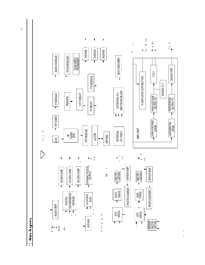
                                                                                                                                                                                       Block Diagrams


10. Block Diagrams


                                                                                    SIGNAL PART


              SPEAKER R
                                AUDIO AMP                                           LNA            RF TUNER        IF MODULE                   AUDIO MODULE
              SPEAKER L
                                                          R-CONV.AMP
               H-BLK                                                      R-CY
                                          DIGITAL                                                                 PEAKING                      PICTURE BOOST
                                                                                         RF
                                        CONVERGENCE        G-CONV.AMP                  TUNER
                          V-BLK                                           G-CY
                          _ 5.7V
                          +               MODULE                                        (PIP)                                                   R,G,B VIDEO
                                                           B-CONV.AMP                                                                           PROCESSOR
                                                                          B-CY                                    CTI/Y-DELAY

                                                                                    PIP MODULE                                                            R-DRIVE              R CRT
                      H-PARA              H/V-PARA        DYNAMIC FOCUS
                                            SUM              OUTPUT       FOCUS                               1H DELAY          TTX MODULE
                               V-PARA                                     PACK       m-COM                                                                G-DRIVE            G CRT

             CONVERGENCE PART
                                                                                                                                                          B-DRIVE              B CRT
                                                              SMPS PART             E2PROM


                                STR            MAIN         RECTIFI-                 EXTERNAL                  EXTERNAL A/V                  MULTI DECODER
                               S6709           TRANS        CATION        DEFL &
                                                                          SIGNAL     A/V INPUT                SWITCHING BLOCK

                                          PHOTO COUPLER      ERROR AMP
                                                                                                                                                                  D.Y
                                                                                                                                                                VERTICAL
                                STR             SUB         RECTIFI-                   DEFL PART
                               S6709           TRANS        CATION        CONV. &                                 V-AMP & E/W CORRECTION                             CRT
                                                                          SOUND                                                                                 HIGH VOLTAGE
                  BRIDGE                 PHOTO COUPLER      ERROR AMP
                  RECTIFI-                                                                HIGH VOLTAGE        HIGH VOLTAGE                                          SCREEN
                  CATION                                                                                                                  FBT
                                                                                              DRIVE             OUTPUT TR

                                                                                                                            DUMMY D.Y
                                                                                                                                                                   D.Y
                                                                                          HORIZONTAL          HORIZONTAL                                       HORIZONTAL
                                                                                             DRIVE             OUTPUT TR                DUMMY FBT


Samsung Electronics                                                                                                                                                                             10-1
                                                              Schematic Diagrams


12. Schematic Diagrams
12-1 SIGNAL (MICOM,TTX, B+ , AV-S/W)


                                       TP91
                                                       TP92


                                                TP93

                                              TP94


                                                                  : Power Line
                                                                  : Signal Line


Samsung Electronics                                                         12-1
Schematic Diagrams


12-2 SIGNAL(PIP-IF, AUDIO-MODULE)


                                    TP4


                                                TP6


                                          TP3


                                    TP2


                             TP1

                                                      TP5


                                                                  : Power Line
                                                                  : Signal Line


12-2                                                        Samsung Electronics
                                                                      Schematic Diagrams


12-3 SIGNAL (VIDEO, CHROMA, PEAKING)


                                 TP22


                                        TP28


                                               TP24


                                                        TP25
                                                               TP27
                                                        TP26
                                                 TP23


                      TP21

                                                                          : Power Line
                                                                          : Signal Line


Samsung Electronics                                                                 12-3
Schematic Diagrams


12-4 SIGNAL (CONV, KARAOKE, COMB-PART)


                     TP30

  TP29


                                         TP32


                                                TP31


                                                             : Power Line
                                                             : Signal Line


12-4                                                   Samsung Electronics
                                                   Schematic Diagrams


12-5 P0WER


                              TP83
                                     TP81
                                            TP82


                                        TP84


                      TP87
                       TP86


                                 TP85


                                                       : Power Line
                                                       : Signal Line


Samsung Electronics                                              12-5
Schematic Diagrams


12-6 DEFL


                                            TP39


                                          TP38


                                                   TP42
                     TP37


                                                          TP43
                                   TP41


                                                                       : Power Line
                                                                       : Signal Line
                            TP44


12-6                                                             Samsung Electronics
                                                                                              Schematic Diagrams


12-7 CONVER.


                                                                       TP62
                                                                TP61


                      TP70


                                           TP71


                                                  TP69                 TP64
                                                                TP63


                                    TP68


                                                                                     TP66


                             TP67

                                                         TP65


                                                                              : Power Line
                                                                              : Signal Line


Samsung Electronics                                                                                        12-7
Schematic Diagrams


12-8 CRT


                                           TP51


                             TP53


                      TP52


                                            TP54


                                    TP55

                                            TP56


                     TP57


12-8                                               Samsung Electronics
                      Schematic Diagrams


12-9 PWB-PIP


                          : Power Line
                          : Signal Line


Samsung Electronics                 12-9
Schematic Diagrams


12-10 AUDIO-MODULE


                           : Power Line
                           : Signal Line


12-10                Samsung Electronics
                      Schematic Diagrams


12-11 IF


                          : Power Line
                          : Signal Line


Samsung Electronics               12-11
Schematic Diagrams


12-12 TTX


                     : Power Line
                     : Signal Line


12-12                        Samsung Electronics
                                                             Schematic Diagrams


12-13 CONTROL-JACK-A, CONTROL-DOOR,PRE-AMP


                                             : Power Line
                                             : Signal Line


Samsung Electronics                                                      12-13
Schematic Diagrams


12-14 A/V-SWITCHING


                                      TP34


                      TP33


                             TP35   TP36


12-14                                        Samsung Electronics
                       Schematic Diagrams


12-15 MIC.MASTER S/W


Samsung Electronics                12-15
Schematic Diagrams


                                   TP13
                            TP12
                     TP11

                                     TP14


                                     TP15


                                     TP16


                                    TP17


                                    TP18


12-16                                       Samsung Electronics
                                                                                                                                                                        Wiring Diagram


11. Wiring Diagram


                                                                                                            CTRL-MIC


                                                                                                    CNE01
                                                 CN902
                           CTRL-DOOR                                   CRTL-JACK                                                                 CRT-R
                                                                                                                                                                  H/V
                                                    CN802
                                                    CN803                                                     POWER
                                                                                                                                       CN503-1     CN503 CN504
                                                                         CN904 CN901
                      R
                      G                         FOUCS PACK                                            CN801
                                                  CN601                                               CN905
                      B   CONVERGENCE                                    SIGNAL                                        CN201                     CRT-G
                                                                                          CN701
                                                                                                                                                                 H/V


                             CN203 CN202    CNZ01         CNQ01                             CN702             PREAMP           CN501
                                                                                                                                       CN502-1     CN502 CN505
                                                         LNA     CN201      CN202
                                                                                     VM
                                                                                              R
                                                                                              G
                            CONVG.                                     DEFLECTION
                                                                                               B            A/V BACK                             CRT-B
                            MODULE
                                                                                                                                                                 H/V

                                        CN401
                                                               FOCUS               SCREEN
                                                                       R, G, B, DY                          CNH01


Samsung Electronics                                                                                                                                                              11-1
                                                                                                                              Troubleshooting


6. Troubleshooting


6-1 No Power


                           Abnormal 0V                   Check CN801 Pin 2                      Normal 12V
                                                             (STB B + ).


      Abnormal                           Normal                                   3V                                          0V
                      Check C801                                                                     Check the voltage
                                                                                                      on CN801 Pin 1


  Check/Replace                          Check/Replace          Normal                          Abnormal                    Check IC901
  D808 & R801                                                                Check F851.
                                         HC801                                                                                 (VCC)


                                                                                              Check/Replace
                                                                                              Q401 and Q402


                                                                                               Replace F854


                                   Normal 0V        Check the base voltage       Abnormal 0.6V
                                                           on Q852


                              Check/Replace                                      Check/Replace
                              Q851 and Q852.                                         Q854.


                                                                                           Normal

                                                                                                                         Abnormal


                                                                                 Check IC901                               Replace IC901
                                                                               Peripheral Circuits


Samsung Electronics                                                                                                                        6-1
Troubleshooting


6-2 No Picture


                     Check TDA4780          Normal
                   (IC203) Pin 1, Pin 13
                        Low-High

                                             Check/Replace
                              Abnormal       m-com (IC901


                  Check TDA9160 (IC202)    Abnormal
                     Y-output (Pin 1)


                                               Replace
                              Normal        TDA9160 (IC202)


                     Check TDA4780         Abnormal
                     Y-input (Pin 8)


                                            Check/Replace
                              Normal            IC203


                   Check Pin 8 of IC501,
                   IC502, IC503


6-2                                                           Samsung Electronics
                                                                                                                       Troubleshooting


6-3 No Sound


                      Normal (_28V)
                              +                                                               Abnormal (0V)
                                                         Check pins 9 and 11
                                                             of HC651


                                                                                                 Check D859,D860,
                Check the Pin 5               Abnormal
               of the CN601(mute)                                                             F852, F853 on the SMPS


                                             Check/Replace RL651
                           Normal             and m-com (IC901


              Check pins 3 and 5 of                      Normal
               the Audio module


                          Abnormal


                Check/Replace                      Abnormal            Check pins 24 and 22
                upc1853 (IC602)                                          of the Audio mdl


                                        Check/Replace KA2192,                    Normal
                                      TC4053BP on the A/V switch


                                                         Abnormal      Check pins 16 and 18      Normal
                                                                         of the audio mdl


                                                 Check/Replace                                   Check/Replace
                                                   TDA9840                                           IC601


Samsung Electronics                                                                                                               6-3
Troubleshooting


6-4 Horizontal Line


                                      Normal                     Check the Waveform of                Abnormal
                                                                    IC202 Pin 15,16


                           Check IC301 and its                                                        Check IC202 and its
                           peripheral circuits                                                        peripherial circuits


6-5 Convergence Misaligned


                                                                         Check
                                     Normal                     the waveform of each                   Abnormal
                                                           terminal in Convergence Module
                                                                        CN203


             Normal        Check the voltage on      Abnormal                                        Check the Waveform of           Abnormal
                                                                                       Normal
                             CN803 pins 4,6                                                        each terminal in Convergence
                                                                                                          Module CN202

                                                  After checking the _ 26V
                                                                      +                                                           Check the Circuits
  Check the Differential                                                     Replace the
                                                  load line, check/replace                                                        Connected to each
  Amplifier of each                                                          Convergence Module.
                                                  the Fuse F854, F855 on                                                          terminal of Convergence
  Convergence terminal
                                                  the SMPS board                                                                  Module CN202


6-4                                                                                                                               Samsung Electronics
5. Alignment and Adjustments

5-1 RF AGC Adjustment                                 5-4 FBT B+ Voltage Adjustment
1. Tune to the strongest local station.               PREPARATION

2. Turn the AGC control fully clockwise (VR111,       1. Note: The B+ voltage adjustment (FBT) is
   on the IF board).                                     done during the chassis check at the factory.
                                                         Perform this adjustment after Sub-Brightness
3. Adjust the AGC control until noise (snow)             and Convergence.
   disappears from the screen.
                                                      2. Warm up the TV for at least for 10 minutes.
5-2 Screen Adjustment
                                                      3. Input 100% white pattern.
1. Turn to the Active channel.
                                                      4. Select the "STANDARD" video mode.
2. Adjust the VR (VR501, VR531, VR561) screen
                                                      ADJUSTMENT
   for a normal picture is (no blooming or flyback
   line).
                                                      1. Connect the leads of a multimeter to GT405
3. Adjust the FOCUS control for well defined             (B+) and GT406(G).
   scanning lines in the center area of the screen.
                                                      2. Set VR401 (on deflection board) to either
                                                         126.9V (for NTSC), or 125.6V (for PAL).
5-3 Horizontal Dynamic Focus
    Adjustment

PREPARATION
1. Input a crosshatch pattern.

2. Cover the Red and Blue Lenses.

3. Enter "STANDARD" video mode.

4. Adjust the Green Lens for best focus.

ADJUSTMENT
Adjust VRZ01 (located on the convergence board).
Balance the left and right sides of the dynamic
focus lines.


          Fig. 5-1 Balance the left and right sides


Samsung Electronics                                                                                    5-1
Alignment and Adjustments


5-5 Lens Focus and Static Focus
    Adjustment
5-5-1 Static Focus (Electric Focus)                           5-5-2 Lens Focus

PREPARATION                                                   PREPARATION
1. Select the "STANDARD" video mode.                          1. Do this adjustment after the static focus
                                                                 adjustment .
2. Input a crosshatch pattern.
                                                              2. Select the " STANDARD" video mode.
3. Cover the lenses that are not being adjusted.                 (Contrast: 64, Brightness: 32)

4. Connect a convergence jig and read data.                   3. Input a cross hatch pattern.

5. Adjust the lens for best focus.                            ADJUSTMENT

ADJUSTMENT                                                    1. Loosen the lens screws.

Vary the focus pack VR (Red, Blue) on the front               2. Cover the two lenses that are not being
cabinet. Adjust the TV for best possible focus                   adjusted.
around the center of the crosshatch pattern,
without losing overall screen balance.                        3. Adjust the lens, observing the color aberration
                                                                 vertically and horizontally within 3 blocks of
                                                                 the center of the crosshatch pattern.

                                                              4. When the lens is turned clockwise, the color
                                                                 aberration will change as follows:
                                                                   Lens        Color Aberration Change
                                                                   R           Orange --- Crimson
 Fig. 5-2 Crosshatch Pattern. Examine these points together        G           Blue --- Red
                                                                   B           Purple --- Green
                                                              5. Green lens adjustment:
                                                                 Set the lens at the point where Blue just
                                                                 changes to Red. If the color aberration is
                                                                 irregular throughout the picture screen,
                                                                 adjust the lens to show Red within a 3-block
                                                                 grid around the horizontal center-line.

                                                                 Observe the the color aberration near the
                                                                 intersection points of the horizontal and
                                                                 vertical lines (approximately 1 - 3 mm area).
                                                                 If the aberration is irregular, adjust the lens as
                                                                 shown in the diagram below. (Accurate
                                                                 alignment of Green is important for overall
                                                                 color quality.)
                  Fig. 5-3 Color Aberration
                                                              6. Set the Red lens at the point where Orange
                                                                 becomes Crimson.

                                                              7. Set the Blue lens at the point where Purple
                                                                 becomes Green.


5-2                                                                                              Samsung Electronics
                                                                                    Alignment and Adjustments


5-6 Convergence Adjustment

5-6-1 Convergence Adjustment

1. Input a PAL pattern.                             11. Adjust Blue as above.

2. Warm up the set for 30 minutes before            12. After the adjustments are completed, press
   adjustment.                                          "Recall" to save the data.

3. Display the test pattern (Crosshatch) by         13. Change from PAL mode to NTSC when
   pressing the remote-control keys in this             making NTSC adjustments.
   sequence : Conv.


◦ Jabse Service Manual Search 2024 ◦ Jabse PravopisonTap.bg ◦ Other service manual resources online : FixyaeServiceinfo