Service Manuals, User Guides, Schematic Diagrams or docs for : Samsung TV samsung_cs-29k3_ch.ks7a_527
<< Back | HomeMost service manuals and schematics are PDF files, so You will need Adobre Acrobat Reader to view : Acrobat Download Some of the files are DjVu format. Readers and resources available here : DjVu Resources
For the compressed files, most common are zip and rar. Please, extract files with Your favorite compression software ( WinZip, WinRAR ... ) before viewing. If a document has multiple parts, You should download all, before extracting.
Good luck. Repair on Your own risk. Make sure You know what You are doing.
Image preview - the first page of the document
>> Download samsung_cs-29k3_ch.ks7a_527 documenatation <<
Text preview - extract from the document
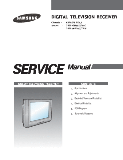
                    DIGITAL TELEVISION RECEIVER
                    Chassis :    KS7A(P) REV.1
                    Model    :   CS29K3MHUX/HAC
                                 CS29M6PQVX/TAW


SERVICE                          Manual

COLOR TELEVISION RECEIVER                      CONTENTS
                                    1. Specifications

                                    2. Alignment and Adjustments

                                    3. Exploded Views and Parts List

                                    4. Electrical Parts List

                                    5. PCB Diagram

                                    6. Schematic Diagrams
                                                                                                                    Specifications


1. Specifications

                 Count ry                                                       INDEX

            Or igin Mark               Made in Local Country(Fact ory) or Made By Samsung

            C ol o r
                                       PAL/SECAM/NTSC4 . 43/NTSC3. 58(NTSC3.58 is option) , ( SECAM-L' , L is option)
            demodulat ion

             Sound
                                       Quas i - s p l i t ( Related t o VCTI)
             receving way

            Sound
        F                               Vi rt ual Dol by/Nicam/St ereo/Line St ereo
            demodulat ion
        I
            Ant enna                    75ohmDin - Jack( V/U)
        X
        E C hannel s earch              Pr ogrammable F/S

        D C hnnel numbers               100 CH PROGRAM MEMORY

                                        Eas t - As ia, Middle- East As ia , Afr ica( 100V ~ 260V ) ,
             I nput voltage
                                        Cis ( 160V ~ 300V) , Europe( 230V) , 240V
             Po wer Input
                                        50/60H z
             fr e quency

            Power STR                   Fr ee Vol t ( X6757) , Single Volt ( X6750)

             Pow er insulat ion         SMPS/C LD
                                              O

        U    Recei vi ng ( P/G ) C H    V F: 2 ~ 13, U F: 14 ~ 69, C TV: S1~S41
                                         H            H             A
        n
             BRAND / BUYER              SAMSUNG/Depend on t he Buyer
        f
        i    S afet y                  Depend on t he count ry
        x
            Pow er cord/
        e                              CP2/No( 4. 0) , AP 2/Yes , EP2/No
             Polar it y
        d

                                        * 2T- PI P/1T- PI P/ No PIP
                                        * ANT display( Opt ion)
               Cha r act e r
                                        * DNIe Jr ( Opt ion)
                                        * FM Radio(Opt ion)


Samsung Electronics                                                                                                           1-1
                                                                                     Alignment and Adjustments


2. Alignment and Adjustments
2-1 General Alignment Instructions

1. Usually, a color TV-VCR needs only slight            5. Avoid overload. Excessive signal from a
   touch-up adjustment upon installation. Check            sweep generator might overload the front-end
   the basic characteristics such as height,               of the TV. When inserting signal markers, do
   horizontal and vertical sync and focus.                 not allow the marker generator to distort test
                                                           results.
2. Observe the picture for good black and white
   details. There should be objectionable color         6. Connect the TV only to an AC power source
   shading; if color shading is present,                   with voltage and frequency as specified on the
   demagnetize, perform purity and convergence             backcover nameplate.
   adjustments described below.
                                                        7. Do not attempt to connect or disconnect any
3. Use the specified test equipment or its                 wires while the TV is turned on. Make sure
   equivalent.                                             that the power cord is disconnected before
                                                           replacing any parts.
4. Correct impedance matching is essential.
                                                        8. To protect against shock hazard, use an
                                                           isolation transformer.

2-2 Automatic Degaussing
    A degaussing coil is mounted around the                If the chassis or parts of the cabinet become
    picture tube, so that external degaussing after        magnetized, poor color purity will result. If
    moving the TV should be unnecessary. But               this happens, use an external degaussing coil.
    the receiver must be properly degaussed upon           Slowly move the degaussing coil around the
    installation.                                          faceplate of the picture tube and the sides and
                                                           front of the receiver. Slowly withdraw the coil
    The degaussing coil operates for about 1               to a distance of about 6 feet before turning
    second after the power is switched ON. If the          power OFF.
    set is moved or turned in a different direction,
    the power should be OFF for at least 10                If color shading persists, perform the
    minutes.                                               following Color purity and Convergence
                                                           adjustments.

2-3 High Voltage Check
    CAUTION : There is no high voltage adjustment
    on this chassis. The B+ power supply should be
    +135 volts (with full color- bar input and normal
    picture level).

1. Connect a digital voltmeter to the second
   anode of the picture tube.

2. Turn on the TV. Set the Brightness and
   Contrast controls to minimum (zero beam
   current).

3. Adjust the Brightness and contrast controls to
   both extremes. Ensure that the high voltage
   does not exceed 30 KV under any conditions.


Samsung Electronics                                                                                       2-1
Alignment and Adjustments


2-4 FOCUS Adjustment

1. Iput a crosshatch pattern.

2. Adjust the tuning control for the clearest picture.

3. Adjust the FOCUS control for well defined scanning lines in the center area of the screen.


2-5 SCREEN Adjustment
1. Input Toshiba Pattern
   If a Toshiba pattern is not available,
   Enter "Service Mode" and
   select "Test pattern 2"(Toshiba pattern)
                                                              ex) IBRM = 175
2. Enter "Service Mode".                                          WDRV = 110
                                                                  CDL = 250
3. Select "G2-Adjust".                                            COLR G B = 110 110 110

4. Set the values as example

5. Turn the SCREEN VR until "Read Cutoff" and "Read Drive" are green.
   (The incorrect SCREEN Voltage may result that "Read Cutoff" and "Read Drive" should be red)


2-6 White Balance Adjustment
1. Warm up the TV set for at least 30 minutes.

2. Enter the Service Mode by pressing the remote control keys in the following sequence:
  Power Off
◦ Jabse Service Manual Search 2026 ◦ Jabse Pravopis ◦ onTap.bg ◦ Other service manual resources online : Fixya ◦ eServiceinfo