Service Manuals, User Guides, Schematic Diagrams or docs for : Sharp Copiers SF2314_2414_2514 SF2314SM
<< Back | HomeMost service manuals and schematics are PDF files, so You will need Adobre Acrobat Reader to view : Acrobat Download Some of the files are DjVu format. Readers and resources available here : DjVu Resources
For the compressed files, most common are zip and rar. Please, extract files with Your favorite compression software ( WinZip, WinRAR ... ) before viewing. If a document has multiple parts, You should download all, before extracting.
Good luck. Repair on Your own risk. Make sure You know what You are doing.
Image preview - the first page of the document
>> Download SF2314SM documenatation <<
Text preview - extract from the document
SERVICE MANUAL
CODE: 00ZSF2314SM1E
Copier
SF-2414
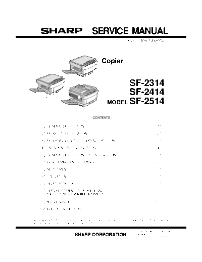
MODEL SF-2314
MODEL SF-2414
SF-2314
MODEL SF-2514
SF-2514
CONTENTS
[ 1 ] GENERAL DESCRIPTION . . . . . . . . . . . . . . . . . . . . . . . . . . . . . . . . . . . . . . . . . . 1-1
[ 2 ] PRODUCT SPECIFICATIONS . . . . . . . . . . . . . . . . . . . . . . . . . . . . . . . . . . . . . . . 2-1
[ 3 ] EXTERNAL VIEW AND INTERNAL STRUCTURE . . . . . . . . . . . . . . . . . . . . . . . 3-1
[ 4 ] UNPACKING AND INSTALLATION . . . . . . . . . . . . . . . . . . . . . . . . . . . . . . . . . . 4-1
[ 5 ] GENERAL DESCRIPTIONS OF EACH SECTION . . . . . . . . . . . . . . . . . . . . . . . 5-1
[ 6 ] DISASSEMBLY AND ASSEMBLY . . . . . . . . . . . . . . . . . . . . . . . . . . . . . . . . . . . 6-1
[ 7 ] ADJUSTMENTS . . . . . . . . . . . . . . . . . . . . . . . . . . . . . . . . . . . . . . . . . . . . . . . . . . 7-1
[ 8 ] SIMULATIONS . . . . . . . . . . . . . . . . . . . . . . . . . . . . . . . . . . . . . . . . . . . . . . . . . . . 8-1
[ 9 ] SELF DIAGNOSTICS . . . . . . . . . . . . . . . . . . . . . . . . . . . . . . . . . . . . . . . . . . . . . 9-1
[10] SERVICE AT MEMORY TROUBLE AND
[10] MAIN CONTROL PWB REPLACEMENT . . . . . . . . . . . . . . . . . . . . . . . . . . . . . 10-1
[11] MAINTENANCE . . . . . . . . . . . . . . . . . . . . . . . . . . . . . . . . . . . . . . . . . . . . . . . . . 11-1
[12] ELECTRICAL SECTION . . . . . . . . . . . . . . . . . . . . . . . . . . . . . . . . . . . . . . . . . . 12-1
Parts marked with "!" is important for maintaining the safety of the set. Be sure to replace these parts with specified
ones for maintaining the safety and performance of the set.
This document has been published to be used
SHARP CORPORATION for after sales service only.
The contents are subject to change without notice.
CONTENTS
[ 1 ] GENERAL DESCRIPTION ................... 1-1 5-1. General descriptions . . . . . . . . . . . . . . . . . . . . . . . .5-3
1. Features . . . . . . . . . . . . . . . . . . . . . . . . . . . . . . . . . . . . 1-1 (1) Original table . . . . . . . . . . . . . . . . . . . . . . . . .5-3
2. Target users . . . . . . . . . . . . . . . . . . . . . . . . . . . . . . . . . 1-1 (2) Copy lamp . . . . . . . . . . . . . . . . . . . . . . . . . . .5-3
3. System outline . . . . . . . . . . . . . . . . . . . . . . . . . . . . . . . . 1-1 (3) Mirror . . . . . . . . . . . . . . . . . . . . . . . . . . . . . . .5-3
(4) Lens (Fixed focus lens) . . . . . . . . . . . . . . . . .5-3
[ 2 ] PRODUCT SPECIFICATIONS . . . . . . . . . . . . . . . 2-1
(5) Lens home position sensor (LHPS) . . . . . . . .5-3
1. Basic specifications . . . . . . . . . . . . . . . . . . . . . . . . . . . 2-1
(6) Lens base . . . . . . . . . . . . . . . . . . . . . . . . . . . .5-3
2. Details of each section . . . . . . . . . . . . . . . . . . . . . . . . . 2-1
(7) Lens drive shaft . . . . . . . . . . . . . . . . . . . . . . .5-4
3. Supplies . . . . . . . . . . . . . . . . . . . . . . . . . . . . . . . . . . . . 2-3
(8) Lens drive wire . . . . . . . . . . . . . . . . . . . . . . . .5-4
[ 3 ] EXTERNAL VIEW AND INTERNAL (9) No. 4/5 mirror base . . . . . . . . . . . . . . . . . . . .5-4
STRUCTURE . . . . . . . . . . . . . . . . . . . . . . . . . . . . . . . 3-1 (10) Mirror motor . . . . . . . . . . . . . . . . . . . . . . . . . .5-4
1. External view and internal structure (11) Mirror home position sensor (MHPS) . . . . . . .5-4
(SF-2514 as the example model) . . . . . . . . . . . . . . . . . 3-1
(12) No. 2/3 mirror base . . . . . . . . . . . . . . . . . . . .5-4
2. Operation panel . . . . . . . . . . . . . . . . . . . . . . . . . . . . . . . 3-2
(13) Copy lamp unit . . . . . . . . . . . . . . . . . . . . . . .5-4
3. Cross section (SF-2514 as the example model) . . . . . . 3-3
(14) Thermal fuse . . . . . . . . . . . . . . . . . . . . . . . . .5-4
4. Switches, sensors, detectors
(15) Reflector . . . . . . . . . . . . . . . . . . . . . . . . . . . . .5-4
(The SF-2514 as the typical example) . . . . . . . . . . . . . 3-4
(16) Exposure adjustment plates . . . . . . . . . . . . . .5-4
5. Clutches, solenoids
(The SF-2514 as the typical example) . . . . . . . . . . . . . 3-5 (17) Mirror base drive wire . . . . . . . . . . . . . . . . . . .5-4
6. Motors (The SF-2514 as the typical example) . . . . . . . 3-6 (18) Lens drive motor . . . . . . . . . . . . . . . . . . . . . .5-4
7. PWBs (The SF-2514 as the typical example) . . . . . . . . 3-7 (19) AE sensor . . . . . . . . . . . . . . . . . . . . . . . . . . . .5-4
5-2. Basic operations . . . . . . . . . . . . . . . . . . . . . . . . . . .5-4
[ 4 ] UNPACKING AND INSTALLATION . . . . . . . . . 4-1
6. Copy process . . . . . . . . . . . . . . . . . . . . . . . . . . . . . . . . .5-6
1. Packing drawing . . . . . . . . . . . . . . . . . . . . . . . . . . . . . . 4-1
(1) Photoconductor . . . . . . . . . . . . . . . . . . . . . . . . . . .5-6
2. Installation . . . . . . . . . . . . . . . . . . . . . . . . . . . . . . . . . . 4-1
(2) Process diagram . . . . . . . . . . . . . . . . . . . . . . . . . . .5-6
(1) Environment . . . . . . . . . . . . . . . . . . . . . . . . . . . . . . . 4-1
(3) Actual process . . . . . . . . . . . . . . . . . . . . . . . . . . . .5-7
(2) Space around the machine . . . . . . . . . . . . . . . . . . . 4-2
(4) Transit of photoconductor drum surface
(3) Installing table . . . . . . . . . . . . . . . . . . . . . . . . . . . . . 4-2 potential . . . . . . . . . . . . . . . . . . . . . . . . . . . . . . . .5-11
(4) Power source . . . . . . . . . . . . . . . . . . . . . . . . . . . . . . 4-3 (5) Process correction system . . . . . . . . . . . . . . . . . .5-12
(5) Grounding . . . . . . . . . . . . . . . . . . . . . . . . . . . . . . . . 4-3 1) Outline of the correction system . . . . . . . . . . .5-12
3. Installation procedure . . . . . . . . . . . . . . . . . . . . . . . . . . 4-3 2) Correction operation . . . . . . . . . . . . . . . . . . . .5-12
(1) Optical system unlocking . . . . . . . . . . . . . . . . . . . . . 4-3 7. SPF section (SF-2514 only) . . . . . . . . . . . . . . . . . . . . .5-14
(2) Cassette setting . . . . . . . . . . . . . . . . . . . . . . . . . . . . 4-3 1. Outline . . . . . . . . . . . . . . . . . . . . . . . . . . . . . . . . . . .5-14
(3) Developer setting . . . . . . . . . . . . . . . . . . . . . . . . . . . 4-4 [ 6 ] DISASSEMBLY AND ASSEMBLY . . . . . . . . . . . 6-1
(4) Toner supply . . . . . . . . . . . . . . . . . . . . . . . . . . . . . . 4-5 1. Paper feed section, paper transport section,
(5) Toner density sensor level check . . . . . . . . . . . . . . 4-5 power section . . . . . . . . . . . . . . . . . . . . . . . . . . . . . . . . .6-1
(6) Accessory attachment . . . . . . . . . . . . . . . . . . . . . . . 4-6 1-1. Paper feed unit . . . . . . . . . . . . . . . . . . . . . . . . . . .6-1
4. Locking procedure for transit or repacking . . . . . . . . . . 4-6 1-2. Paper feed roller ass'y removal . . . . . . . . . . . . . .6-1
(1) No.2/No.3 mirror unit (Mirror base B) lock . . . . . . . 4-6 1-3. Separation roller . . . . . . . . . . . . . . . . . . . . . . . . .6-2
(2) No.4/no.5 mirror unit (Mirror base C) lock . . . . . . . 4-6 1-4. Takeup roller, paper feed roller . . . . . . . . . . . . . .6-2
5. Optional paper feed unit (SF-CM14), 1-5. Resist roller . . . . . . . . . . . . . . . . . . . . . . . . . . . . . .6-3
Installation Manual . . . . . . . . . . . . . . . . . . . . . . . . . . . . 4-7 1-6. Transport belt . . . . . . . . . . . . . . . . . . . . . . . . . . . .6-4
(1) Set the main copier unit on the paper feed unit. . . . 4-7 1-7. Socket holder unit . . . . . . . . . . . . . . . . . . . . . . . . .6-4
(2) Remove the paper tray from the main copier unit. . . 4-7 1-8. Lower unit PWB . . . . . . . . . . . . . . . . . . . . . . . . . .6-4
(3) Open the upper unit of the main copier unit. . . . . . . 4-7 1-9. Cassette paper empty detector (CPED1) . . . . . . .6-4
(4) Connect the main copier unit and 1-10. Power unit . . . . . . . . . . . . . . . . . . . . . . . . . . . . . . .6-4
the paper feed unit. . . . . . . . . . . . . . . . . . . . . . . . . . 4-8
2. Manual paper feed section . . . . . . . . . . . . . . . . . . . . . . .6-5
6. Optional multi bypass feeder unit Installation Manual . . 4-8
2-1. Manual paper feed roller, manual takeup roller . . .6-5
(1) Open the upper unit of the main copier unit. . . . . . . 4-8
2-2. Reverse rotation roller ass'y . . . . . . . . . . . . . . . . . .6-5
(2) Release the lock for the manual bypass unit and
3. Fuser section . . . . . . . . . . . . . . . . . . . . . . . . . . . . . . . . .6-6
remove the manual bypass unit. . . . . . . . . . . . . . . . 4-8
3-1. Fuser unit removal . . . . . . . . . . . . . . . . . . . . . . . . .6-6
(3) Mount the multi bypass feeder unit onto
3-2. Heater lamp replacement . . . . . . . . . . . . . . . . . . . .6-6
the main copier unit. . . . . . . . . . . . . . . . . . . . . . . . . 4-9
3-3. Upper heat roller ass'y removal . . . . . . . . . . . . . . .6-7
[ 5 ] GENERAL DESCRIPTIONS OF 3-4. Upper separation pawl replacement . . . . . . . . . . . .6-7
EACH SECTION . . . . . . . . . . . . . . . . . . . . . . . . . . . . 5-1
3-5. Lower cleaning roller and
1. Paper feed section . . . . . . . . . . . . . . . . . . . . . . . . . . . . 5-1 lower heat roller replacement . . . . . . . . . . . . . . . . .6-7
2. Separation, transport section . . . . . . . . . . . . . . . . . . . . 5-2 3-6. Scraper replacement . . . . . . . . . . . . . . . . . . . . . . .6-8
3. Fuser, paper exit section . . . . . . . . . . . . . . . . . . . . . . . 5-2 3-7. Thermistor/thermostat removal . . . . . . . . . . . . . . . .6-8
4. Developer section . . . . . . . . . . . . . . . . . . . . . . . . . . . . 5-2 4. Optical system . . . . . . . . . . . . . . . . . . . . . . . . . . . . . . . .6-9
5. Optical system . . . . . . . . . . . . . . . . . . . . . . . . . . . . . . . . 5-3 4-1. Copy lamp replacement . . . . . . . . . . . . . . . . . . . . .6-9
I
4-2. Copy lamp unit replacement . . . . . . . . . . . . . . . . . 6-9 G. Copy density adjustment in the SPF
4-3. Mirror base drive wire replacement . . . . . . . . . . . . 6-9 copy mode . . . . . . . . . . . . . . . . . . . . . . . . . . . .7-28
4-4. Lens and lens drive wire replacement (6) Copy density adjustment table . . . . . . . . . . . . . . .7-29
(Only the zoom function model) . . . . . . . . . . . . . 6-10 4. Others . . . . . . . . . . . . . . . . . . . . . . . . . . . . . . . . . . . . . .7-30
4-5. No. 4/5 mirror unit and (1) Transfer charger wire installation . . . . . . . . . . . . .7-30
peripheral parts replacement . . . . . . . . . . . . . . . 6-11 (2) DV bias adjustment . . . . . . . . . . . . . . . . . . . . . . .7-30
4-6. Optical unit removal . . . . . . . . . . . . . . . . . . . . . . 6-11 (3) Separation charger output adjustment . . . . . . . . .7-30
4-7. Other parts in the optical system . . . . . . . . . . . . . 6-11
[ 8 ] SIMULATIONS . . . . . . . . . . . . . . . . . . . . . . . . . . . . . . .8-1
4-8. Light adjustment plate/temperature fuse
1. Outline . . . . . . . . . . . . . . . . . . . . . . . . . . . . . . . . . . . . . .8-1
removal . . . . . . . . . . . . . . . . . . . . . . . . . . . . . . . 6-12
2. Purpose . . . . . . . . . . . . . . . . . . . . . . . . . . . . . . . . . . . . .8-1
5. SPF section . . . . . . . . . . . . . . . . . . . . . . . . . . . . . . . . 6-13
3. Operating procedure . . . . . . . . . . . . . . . . . . . . . . . . . . . .8-1
5-1. SPF mechanism removal . . . . . . . . . . . . . . . . . . 6-13
4. Purpose list . . . . . . . . . . . . . . . . . . . . . . . . . . . . . . . . . . .8-2
5-2. Paper feed roller/takeup roller replacement . . . . 6-14
5. Details of simulations . . . . . . . . . . . . . . . . . . . . . . . . . . .8-3
5-3. Reverse roller (ass'y) replacement . . . . . . . . . . . 6-14
6. User simulations . . . . . . . . . . . . . . . . . . . . . . . . . . . . . .8-13
5-4. SPF control PWB replacement . . . . . . . . . . . . . . 6-15
5-5. Clutch/solenoid removal . . . . . . . . . . . . . . . . . . . 6-15 [ 9 ] SELF DIAG . . . . . . . . . . . . . . . . . . . . . . . . . . . . . . . . . .9-1
5-6. Sensor removal . . . . . . . . . . . . . . . . . . . . . . . . . 6-15 1. Summary/purpose . . . . . . . . . . . . . . . . . . . . . . . . . . . . .9-1
6. Drum section . . . . . . . . . . . . . . . . . . . . . . . . . . . . . . . 6-16 2. Operation . . . . . . . . . . . . . . . . . . . . . . . . . . . . . . . . . . . .9-1
6-1. Drum unit removal . . . . . . . . . . . . . . . . . . . . . . . . 6-16 3. Clearing the self diag display . . . . . . . . . . . . . . . . . . . . .9-1
7. Developer section . . . . . . . . . . . . . . . . . . . . . . . . . . . 6-16 4. Self diag contents . . . . . . . . . . . . . . . . . . . . . . . . . . . . . .9-2
7-1. Developer unit removal . . . . . . . . . . . . . . . . . . . . 6-16 5. Conditions for the JAM display . . . . . . . . . . . . . . . . . . . .9-7
7-2. Developer cartridge removal . . . . . . . . . . . . . . . 6-16 1) Paper feed section . . . . . . . . . . . . . . . . . . . . . . . . . .9-7
7-3. Toner motor removal . . . . . . . . . . . . . . . . . . . . . 6-17 2) Transport section . . . . . . . . . . . . . . . . . . . . . . . . . . .9-7
7-4. Toner density sensor . . . . . . . . . . . . . . . . . . . . . 6-17 [10] SERVICING AT MEMORY TROUBLE AND
8. Operation panel section/medium cabinet . . . . . . . . . . 6-17 MAIN CONTROL PWB REPLACEMENT . . . .10-1
9. Major parts in the frame side . . . . . . . . . . . . . . . . . . . . 6-18
1. General . . . . . . . . . . . . . . . . . . . . . . . . . . . . . . . . . . . . .10-1
9-1. Ozone filter . . . . . . . . . . . . . . . . . . . . . . . . . . . . . 6-18
2. Purpose . . . . . . . . . . . . . . . . . . . . . . . . . . . . . . . . . . . .10-1
9-2. Optical unit/SPF unit cooling fan removal . . . . . . 6-18
3. Remedies . . . . . . . . . . . . . . . . . . . . . . . . . . . . . . . . . . .10-1
9-3. Ventilation fan motor . . . . . . . . . . . . . . . . . . . . . 6-18
4. Set value recording sheet . . . . . . . . . . . . . . . . . . . . . . .10-4
9-4. Transport roller clutch . . . . . . . . . . . . . . . . . . . . 6-19
5. Memory simulation list . . . . . . . . . . . . . . . . . . . . . . . . .10-5
9-5. Paper exit sensor . . . . . . . . . . . . . . . . . . . . . . . . 6-19
[11] MAINTENANCE . . . . . . . . . . . . . . . . . . . . . . . . . . . . .11-1
[ 7 ] ADJUSTMENTS . . . . . . . . . . . . . . . . . . . . . . . . . . . . . 7-1
1. Developer section . . . . . . . . . . . . . . . . . . . . . . . . . . . . 7-1
[12] ELECTRICAL SECTION . . . . . . . . . . . . . . . . . . . .12-1
1. System block diagram . . . . . . . . . . . . . . . . . . . . . . . . . .12-1
(1) MG roller main pole position adjustment . . . . . . . . . 7-1
2. System operation at power ON . . . . . . . . . . . . . . . . . . .12-1
(2) Adjustment of clearance between DV doctor and MG
roller . . . . . . . . . . . . . . . . . . . . . . . . . . . . . . . . . . . . . 7-2 3. Main circuit . . . . . . . . . . . . . . . . . . . . . . . . . . . . . . . . . .12-2
2. Optical section . . . . . . . . . . . . . . . . . . . . . . . . . . . . . . . . 7-3 (1) Block diagram . . . . . . . . . . . . . . . . . . . . . . . . . . . .12-2
A. Adjustments list . . . . . . . . . . . . . . . . . . . . . . . . . . . . 7-3 (2) CPU (IC110) M37702 . . . . . . . . . . . . . . . . . . . . . .12-2
1 Outline . . . . . . . . . . . . . . . . . . . . . . . . . . . . . . .12-2
B. Notes . . . . . . . . . . . . . . . . . . . . . . . . . . . . . . . . . . . . 7-3
2 Pin arrangement . . . . . . . . . . . . . . . . . . . . . . .12-2
C. Adjustment contents . . . . . . . . . . . . . . . . . . . . . . . . 7-6 3 Block diagram . . . . . . . . . . . . . . . . . . . . . . . . .12-3
(1) Lens . . . . . . . . . . . . . . . . . . . . . . . . . . . . . . . . . . 7-6 4 CPU: M37702 (IC110) pin signals . . . . . . . . . .12-4
(2) Mirror . . . . . . . . . . . . . . . . . . . . . . . . . . . . . . . . 7-7 (3) Start/stop control circuit . . . . . . . . . . . . . . . . . . . .12-5
(3) Image distortion adjustment . . . . . . . . . . . . . . . 7-8
(4) Heater lamp control circuit . . . . . . . . . . . . . . . . . .12-6
(4) Copy image center position adjustment . . . . . 7-12
1 General . . . . . . . . . . . . . . . . . . . . . . . . . . . . . .12-6
(5) Focus adjustment (Resolution adjustment) . . . 7-14
(6) Copy magnification ratio adjustment . . . . . . . . 7-15 (5) Driver circuit (Solenoid, magnetic clutch) . . . . . . .12-7
(7) Uniformity adjustment . . . . . . . . . . . . . . . . . . . 7-18 1 General . . . . . . . . . . . . . . . . . . . . . . . . . . . . . .12-7
(8) Image loss/void area adjustment . . . . . . . . . . . 7-19 2 Operation . . . . . . . . . . . . . . . . . . . . . . . . . . . .12-7
3. COPY DENSITY ADJUSTMENT . . . . . . . . . . . . . . . . 7-26 (6) Stepping motor drive circuit . . . . . . . . . . . . . . . . .12-7
1 General . . . . . . . . . . . . . . . . . . . . . . . . . . . . . .12-7
(1) Copy density adjustment timing . . . . . . . . . . . . . 7-26
(7) AE (Auto Exposure) sensor circuit . . . . . . . . . . . .12-7
(2) Note for copy density adjustment . . . . . . . . . . . . 7-26
(8) Toner supply motor drive circuit . . . . . . . . . . . . . .12-8
(3) Necessary items for the copy density adjustment 7-26
(9) Reset IC (IC113) . . . . . . . . . . . . . . . . . . . . . . . . . .12-8
(4) Copy density adjustment mode . . . . . . . . . . . . . . 7-26
1 Outline . . . . . . . . . . . . . . . . . . . . . . . . . . . . . . .12-8
(5) Copy density adjustment procedure . . . . . . . . . . 7-26 2 Operation . . . . . . . . . . . . . . . . . . . . . . . . . . . .12-8
A. Test chart (UK0G-0162FCZZ) setting . . . . . . 7-26
(10) Copy lamp control section . . . . . . . . . . . . . . . . . .12-9
B. Normal copy mode (Non-toner-save mode)
copy density adjustment . . . . . . . . . . . . . . . . 7-26 4. Operating section . . . . . . . . . . . . . . . . . . . . . . . . . . . .12-11
C. Normal copy mode (Toner save mode) (1) Outline . . . . . . . . . . . . . . . . . . . . . . . . . . . . . . . .12-11
copy density adjustment . . . . . . . . . . . . . . . . 7-27 (2) Display circuit . . . . . . . . . . . . . . . . . . . . . . . . . . .12-12
D. Photo copy mode (Non-toner-save mode) 1 Block diagram . . . . . . . . . . . . . . . . . . . . . . . .12-12
copy density adjustment . . . . . . . . . . . . . . . . 7-27 2 Operation . . . . . . . . . . . . . . . . . . . . . . . . . . .12-12
E. Auto copy mode (Non-toner-save mode) (3) LED display . . . . . . . . . . . . . . . . . . . . . . . . . . . .12-13
copy density adjustment . . . . . . . . . . . . . . . . 7-27
5. Power section . . . . . . . . . . . . . . . . . . . . . . . . . . . . . .12-13
F. Auto copy mode (Toner save mode) copy
density adjustment . . . . . . . . . . . . . . . . . . . . . 7-28 (1) Signal name and output voltage . . . . . . . . . . . . .12-13
II
[1] GENERAL DESCRIPTION
1. Features
[Small] [Soft]
◦ Jabse Service Manual Search 2026 ◦ Jabse Pravopis ◦ onTap.bg ◦ Other service manual resources online : Fixya ◦ eServiceinfo