Service Manuals, User Guides, Schematic Diagrams or docs for : Sony Sony_Microfloppy_Disk_Drive_OA-D32W_OA_D32V_OEM_Manual_Sep83
<< Back | HomeMost service manuals and schematics are PDF files, so You will need Adobre Acrobat Reader to view : Acrobat Download Some of the files are DjVu format. Readers and resources available here : DjVu Resources
For the compressed files, most common are zip and rar. Please, extract files with Your favorite compression software ( WinZip, WinRAR ... ) before viewing. If a document has multiple parts, You should download all, before extracting.
Good luck. Repair on Your own risk. Make sure You know what You are doing.
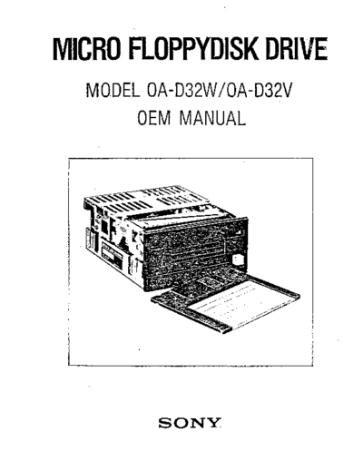
Image preview - the first page of the document

>> Download Sony_Microfloppy_Disk_Drive_OA-D32W_OA_D32V_OEM_Manual_Sep83 documenatation <<
Text preview - extract from the document
MICRO FLOPPYDISK DRIVE
  MO.DEL OA-D32W/OA-D32V
        OEM MANUAL


         SONY
             PROPRIETARY NOTICE

This manual contains proprietary design information.
Reproduction or dissemination of information provided
herein, for purposes other than operation and
maintenance of the equipment, is strictly prohibited
without written consent from the SONY Corporation.


                         I
                      RECORD OF REVISIONS
                                                         ,t-
REVISION                                     NOTES   o


   1               ORIGINAL ISSUE                              September, 1983


               "


           I


           I                        --
           I
           I


                                         n
                                                 CONTENTS


             Descr;pt;on

SECTION 1.   INTRODUCTION ............................................................................................. 1
             1-1.      Purpose ................................................................................................. 1
             1-2.      General Description ............................................................................. 1

SECTION 2.   FUNCTIONAL CHARACTERISTICS ............................................................... 3

             2-1.      General Operation ............................................................................... 3
             2-2.      Read/Write and Control Electronics ................................................... 3
             2-3.      Drive Mechanism ................................................................................. 3
             2-4.      Positioning Mechanism ....................................................................... 4
             2-5.      Disk Chucking Mechanism .................................................................. 4
             2-6.      Read/VVrite Head ............................................................................... '" 4

SECTION 3.   SPECiFICATIONS ............................................................................................. 5

             3-1.      Drive Performance ............................................................................... 5
             3-2.      Dimensional Data ................................................................................ 5
             3-3.      DC Power Requirements ...................................................................... 5
             3-4.      Environmental Considerations ............................................................ 6
                       3-4-1.       Reliability and Maintainability ............................................. 6
                       3-4-2.       Environmental Limits ............................................................. 6

SECTION 4.   INTERFACE DESCRJPTION ................................................. ,........................... 7

             4-1.      Host System Interface ......................................................................... 7
             4-2.      Interface Characteristics ..................................................................... 7
                       4-2-1.       I nput Signal Requirements ......... ........................................... 7
                       4-2-2.       Output Signal Characteristics ............................................... 7
             4-3.      Signal Interface .................................................................................... 7
                       4-3-1.       Input Signal Descriptions ...................................................... 7
                                    4-3-1-1. Dive Select 0.1 (SELECT 0,1 ) .................................. 7
                                    4-3-1-2. Direction Select (DIRTN) ......................................... 9
                                    4-3-1-3. Step (STEP) ................................................................ 9
                                    4-3-1-4. Head Load (HDLOAD) ............................................. 9
                                    4-3-1-5. Write Data(WRTDATA) .......................................... 10
                                    4-3-1-6. Write Gate (WRTGATE) ........................................... 10
                       4-3-2.       Output Signal Descriptions ................................................... 11
                                    4-3-2-1. Index (INDEX) .. ,........................................................ 11
                                    4-3-2-2. TrackOO (TRKOO) .......................................................            l'
                                    4-3-2-3. \Vrite Protect (WRTPRT) .......................................... 12
                                    4-3-2-4. Ready (READy) ......................................................... 12


                                                          m
                                                   CONTENTS


              Description


                                     4-3-2-5. Read Data (RDDAT A) .............................................. 12
                                     4-3-2-6. Motor On (MTON) ................................................... 12
                                     4-3-2-7. Disk Change (DSKCHG) ........................................... 13
                                     4-3-2-8. Disk Change Reset (CHGRST) ................................. 13
                                     4-3-2-9. Head Select (HDSL) .. _............................................... 13
              4-4.       Interface Timing ................................................................................... 14

SECTION S.    CONTROLS AND FRONT PANEL. .................................................................. 15

              5-1.      Operator Contro              .:nd Front Panel.. .... _.............................................. 15
                         5-1-1.       Front ~anel Control ................................................................ 15
                         5-1-2.       Front Pane/Indicator ............................................................. 15
                         5-1-3.       Drive Select Control .............................................................. 15
                         5-1-4.      Disk Motor Control ................................................................ 16

SECTION 6.    OPERATION .................................................................................................... 17

              6-1.       Disk Cartridge Description .................................................................. 17
                        6-1-1.        Disk Cartridge Preparation and Write Protection ................ 17
              6-2.       Operation ............................................................................................. 18
                        6-2-1.        Disk Cartridge Eject ~1echanism ........................................... 18
                         6-2-2.       Disk Cartridge Insertion ......................................................... 18
                         6-2-3.       Disk Cartridge Removal ......................................................... 18
             . 6-3. "" Disk Precautions ................................................................................... 18
              6-4.       Disk Environmental Limits .................................................................. 18

SECTION 7.     ELECTRICAL CONNECTORS .......................................................................... 19

              7-1.       Power Connectors ................................................................................ 19
                         7-1-1.       Frame Ground ........................................................................ 19
                         7-1-2.       DC PowerConnector(CN108) ............................................... 19
                         7-1-3.       DC Power Cable Fabrication ................................................. 19
               7-2.      Signal Interface Connector ................................................................. 20
                         7-2-1.       Signal Interface Connector (C0:109) ..................................... 20
                         7-2-2.       Signal Interface Cable Fabncation ....................................... 20

SECTION 8.     MOUNTING AND INSTALLATION ............................................................... 21

               8-1 .     Orientation ................................................................,...................... .... 21
               8-2.      Installation ........................................................................................... 22
               8-3.      PCB Component locations .................................................................. 23
                                                           l


SECTION 9.     ERROR DETECTION AND CORRECTION .................................................... 24


                                                          IV
                                                  SECTION 1
                                                INTRODUCTION

1-1.   PURPOSE
This material provides the information necessary
to interface the OA-D32W;OA-D32V Micro Flop-
pydisk drive to floppy disk controllers. and pro-
vides the technical specifications for reference in
OEM contracts.

1-2.   GENERAL DESCRIPTION
The SONY Micro Floppydisk Drive represents a                  The SONY proprietary read/write and tunnel erase
◦ Jabse Service Manual Search 2024 ◦ Jabse Pravopis ◦ onTap.bg ◦ Other service manual resources online : Fixya ◦ eServiceinfo