Service Manuals, User Guides, Schematic Diagrams or docs for : Sony TA-N1
<< Back | HomeMost service manuals and schematics are PDF files, so You will need Adobre Acrobat Reader to view : Acrobat Download Some of the files are DjVu format. Readers and resources available here : DjVu Resources
For the compressed files, most common are zip and rar. Please, extract files with Your favorite compression software ( WinZip, WinRAR ... ) before viewing. If a document has multiple parts, You should download all, before extracting.
Good luck. Repair on Your own risk. Make sure You know what You are doing.
Image preview - the first page of the document
>> Download TA-N1 documenatation <<
Text preview - extract from the document
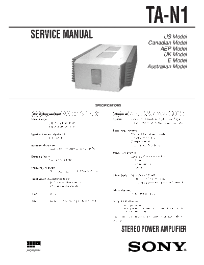
                                            TA-N1
  SERVICE MANUAL                                   US Model
                                            Canadian Model
                                                 AEP Model
                                                   UK Model
                                                     E Model
                                            Australian Model


                   SPECIFICATIONS


                                    STEREO POWER AMPLIFIER

MICROFILM


                                                          1
                    SAFETY CHECK-OUT                                                           TABLE OF CONTENTS

After correcting the original service problem, perform the follow-     1. SERVICE NOTE ................................................................ 3
ing safety checks before releasing the set to the customer:
Check the antenna terminals, metal trim, "metallized" knobs, screws,
                                                                       2. GENERAL ........................................................................... 5
and all other exposed metal parts for AC leakage. Check leakage as
described below.
                                                                       3. ELECTRICAL ADJUSTMENT ..................................... 7
LEAKAGE
The AC leakage from any exposed metal part to earth Ground and         4. DIAGRAMS
from all exposed metal parts to any exposed metal part having a        4-1. Circuit Boards Location ........................................................ 7
return to chassis, must not exceed 0.5 mA (500 microampers). Leak-     4-2. Schematic Diagram
◦ Jabse Service Manual Search 2026 ◦ Jabse Pravopis ◦ onTap.bg ◦ Other service manual resources online : Fixya ◦ eServiceinfo