Service Manuals, User Guides, Schematic Diagrams or docs for : TOSHIBA Copiers E 16 Service manual (eng) information Signal Flow
<< Back | HomeMost service manuals and schematics are PDF files, so You will need Adobre Acrobat Reader to view : Acrobat Download Some of the files are DjVu format. Readers and resources available here : DjVu Resources
For the compressed files, most common are zip and rar. Please, extract files with Your favorite compression software ( WinZip, WinRAR ... ) before viewing. If a document has multiple parts, You should download all, before extracting.
Good luck. Repair on Your own risk. Make sure You know what You are doing.
Image preview - the first page of the document
>> Download Signal Flow documenatation <<
Text preview - extract from the document
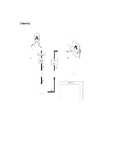
Copying
Original
Drum
Exposure lamp CCD
LSU
IC3
A/D converter
Scanner unit IC11
5
Scanner
contorol IC68
GA
EET
1 4
Scanner
PTC I/F IC36
I/F
PTC GA
2
CODEC I/F-2
IC9,13,15,19 3
PIX-SDRAM IC67
64Mbit x4
CODEC
This machine has two patterns of copying process.
Copying
1
The light irradiated by the exposure lamp to the original is reflected.
Then the CCD reads the reflected light.
The CCD converts the light to an electric signal, and outputs it to the A/D converter (IC3).
The A/D converter converts the electric signal into digital data, and outputs it to the Scanner
control GA (IC11).
The Scanner control GA corrects the image data, and outputs it to the Scanner interface of PTC
GA (IC36) as raster data.
2
The Scanner interface converts the raster data into the parallel.
Then the data is DMA transferred to PIX-SDRAM (IC9, 13, 15, 19) and stored.
3
The raster data is DMA transferred to PTC Interface of PTC GA.
4
The PTC interface transfers the raster data to the EET (IC68) serially.
The EET transfers the raster data to the LSU.
(The EET doesn't provide smoothing for the raster data, and transfers it to the LSU.)
5
The LSU applies the laser beam onto the drum based on the print data, and forms a latent image
on the drum.
The toner adheres on the drum according to the latent image.
Then the data is printed out by transferring the toner onto the recording paper.
Memory Copying
Original
Drum
Exposure lamp CCD
LSU
IC3
A/D converter
Scanner unit IC11
9
Scanner
contorol IC68
GA
EET
1 8
Scanner
PTC I/F IC36
I/F
PTC GA
2
CODEC I/F-2
7
3
IC9,13,15,19 4
PIX-SDRAM IC67
64Mbit x4 5
CODEC
6
5
IC2,3
SRAM
256kbit x2
Memory Copying
1
The light irradiated by the exposure lamp to the original is reflected.
Then the CCD reads the reflected light.
The CCD converts the light to an electric signal, and outputs it to the A/D converter (IC3).
The A/D converter converts the electric signal into digital data, and outputs it to the Scanner
control GA (IC11).
The Scanner control GA corrects the image data, and outputs it to the Scanner interface of PTC
GA (IC36) as raster data.
2
The Scanner interface converts the raster data into the parallel.
Then the data is DMA transferred to PIX-SDRAM (IC9, 13, 15, 19) and stored.
3
The raster data is DMA transferred to CODEC (IC67) via CODEC Interface-2 of PTC GA.
And CODEC converts the raster data into the JBIG data.
4
The JBIG data is DMA transferred to CODEC (IC67) via CODEC Interface-2 of PIX-SDRAM.
Then the JBIG data of all originals to be copied is stored in the SDRAM.
5
The stored JBIG data is DMA transferred to CODEC (IC67) via CODEC Interface-2 of PTC GA.
Then CODEC decodes the JBIG data into the raster data, and stores it in the SRAM.
6
The raster data is DMA transferred to PIX-SDRAM via CODEC Interface-2.
7
The raster data is DMA transferred to PTC Interface of PTC GA.
8
The PTC interface transfers the raster data to the EET (IC68) serially.
The EET transfers the raster data to the LSU.
(The EET doesn't provide smoothing for the raster data, and transfers it to the LSU.)
9
The LSU applies the laser beam onto the drum based on the print data, and forms a latent image
on the drum.
The toner adheres on the drum according to the latent image.
Then the data is printed out by transferring the toner onto the recording paper.
GDI Printer
Drum
PC
LSU
7
IFAX PWA
PC I/F PWA
(Option)
IC68
EET
1 6
PC I/F PTC I/F IC36
PTC GA
2
CODEC I/F-2
5
4
IC9,13,15,19
PIX-SDRAM IC67
64Mbit x4 3
CODEC
3
IC76,77
SRAM
256kbit x2
GDI Printer
1
The coded data is output from the PC.
The coded data is transferred to the PC interface of the PTC GA via PC interface board.
2
The coded data is DMA transferred to PIX-SDRAM (IC9, 13, 15, 19) and stored.
3
The coded data is DMA transferred to CODEC (IC67) via CODEC Interface-2 of PTC GA. Then
CODEC decodes the coded data into the raster data, and stores it in the SRAM.
4
The raster data is DMA transferred to PIX-SDRAM via CODEC Interface-2.
5
The raster data is DMA transferred to PTC Interface of PTC GA.
6
The PTC interface transfers the raster data to the EET (IC68) serially. The EET provides
smoothing for the raster data, and transfers it to the LSU.
7
The LSU applies the laser beam onto the drum based on the print data, and forms a latent image
on the drum.
The toner adheres on the drum according to the latent image.
Then the data is printed out by transferring the toner onto the recording paper.
FAX Direct Transmission
Original
PSTN
Exposure lamp CCD
IC3
A/D converter
Scanner unit IC11
Scanner NCU PWA
contorol
GA
6
1
IC4
Scanner
PTC I/F IC36
I/F V.34 MODEM
PTC GA
2
5
CODEC I/F-1
IC9,13,15,19 IC32
3 4
IC1
PIX-SDRAM System-SDRAM
64Mbit x4 CODEC 64Mbit
3
IC2,3
SRAM
256kbit x2
FAX direct transmission
In the direct transmission, the originals are scanned, and transmitted page by page.
1
The light irradiated by the exposure lamp to the original is reflected.
Then the CCD reads the reflected light.
The CCD converts the light to an electric signal, and outputs it to the A/D converter (IC3).
The A/D converter converts the electric signal into digital data, and outputs it to the Scanner
control GA (IC11).
The Scanner control GA corrects the image data, and outputs it to the Scanner interface of PTC
GA (IC36) as raster data.
2
The Scanner interface converts the raster data into the parallel.
Then the data is DMA transferred to PIX-SDRAM (IC9, 13, 15, 19) and stored.
During this period, this machine also communicates with the destination and determines the
coding method for transmit data.
3
The raster data is DMA transferred to CODEC (IC1) mounted on FAX board via CODEC
Interface-1 of PTC GA.
And CODEC converts the raster data into the coded data (MH, MR, MMR, JBIG).
4
The coded data is DMA transferred to CODEC (IC1) mounted on FAX board via CODEC
Interface-1 of System-SDRAM.
5
The coded data is DMA transferred to MODEM (IC4) mounted on FAX board. And MODEM
modulates the coded data into the analog signals for telephone line.
6
The analog signals are sent to the telephone line network via the NCU board.
Then the data of the original is transmitted to the destination through the telephone line network.
FAX Memory Transmission
Original
PSTN
Exposure lamp CCD
IC3
A/D converter
Scanner unit IC11
Scanner NCU PWA
contorol
GA
10
1
IC4
Scanner
PTC I/F IC36
I/F V.34 MODEM
PTC GA
2
9
CODEC I/F-1
3 4
IC9,13,15,19 IC32
6 5
IC1
PIX-SDRAM System-SDRAM
64Mbit x4 7 CODEC 8 64Mbit
5
IC2,3
SRAM
256kbit x2
FAX memory transmission
The memory transmission reads all the original(s) into memory as transmit data before
transmission.
1
The light irradiated by the exposure lamp to the original is reflected. Then the CCD reads the
reflected light.
The CCD converts the light to an electric signal, and outputs it to the A/D converter (IC3).
The A/D converter converts the electric signal into digital data, and outputs it to the Scanner
control GA (IC11).
The Scanner control GA corrects the image data, and outputs it to the Scanner interface of PTC
GA (IC36) as raster data.
2
The Scanner interface converts the raster data into the parallel.
Then the data is DMA transferred to PIX-SDRAM (IC9, 13, 15, 19) and stored.
During this period, this machine also communicates with the destination and determines the
coding method for transmit data.
3
The raster data is DMA transferred to CODEC (IC1) mounted on FAX board via CODEC
Interface-1 of PTC GA.
And CODEC converts the raster data into the JBIG data.
4
The JBIG data is DMA transferred to CODEC (IC1) via CODEC Interface-1 of System-SDRAM.
Then the JBIG data of all originals to be copied is stored in the SDRAM.
5
The stored JBIG data is DMA transferred to CODEC (IC1) mounted on FAX board via CODEC
Interface-1 of PTC GA.
Then CODEC decodes the JBIG data into the raster data, and stores it in the SRAM.
6
The raster data is DMA transferred to PIX-SDRAM via CODEC Interface-1.
7
The raster data is DMA transferred to CODEC (IC1) mounted on FAX board via CODEC
Interface-1 of PTC GA.
And CODEC converts the raster data into the coded data (MH, MR, MMR, JBIG).
8
The coded data is DMA transferred to CODEC (IC1) mounted on FAX board via CODEC
Interface-1 of System-SDRAM.
9
The coded data is DMA transferred to MODEM (IC4) mounted on FAX board.
And MODEM modulates the coded data into the analog signals for telephone line.
10
The analog signals are sent to the telephone line network via the NCU board.
Then the data of the original is transmitted to the destination through the telephone line network.
FAX Reception
Drum
PSTN
LSU
1
11
NCU PWA
IC68
EET
10
IC4
Scanner
PTC I/F IC36
I/F V.34 MODEM
PTC GA
2
CODEC I/F-1
9
4 3
IC9,13,15,19 IC32
5 6
IC1
PIX-SDRAM System-SDRAM
64Mbit x4 8 CODEC 7 64Mbit
3 7
IC2,3
SRAM
256kbit x2
FAX reception
1
The MODEM (IC4) mounted on FAX board receives analog signals from the telephone line via the
NCU board.
Then the MODEM demodulates the received analog signals into coded data.
2
The coded data is DMA transferred to System-SDRAM (IC32) and stored.
3
The coded data is DMA transferred to CODEC (IC1) mounted on FAX board via CODEC
Interface-1 of PTC GA.
Then CODEC decodes the coded data into the raster data, and stores it in the SRAM.
4
The raster data is DMA transferred to PIX-SDRAM via CODEC Interface-1.
5
The raster data is DMA transferred to CODEC (IC1) mounted on FAX board via CODEC
Interface-1 of PTC GA.
And CODEC converts the raster data into the JBIG data.
6
The JBIG data is DMA transferred to CODEC (IC1) mounted on FAX board via CODEC Interface-
1 of System-SDRAM.
7
The JBIG data is DMA transferred to CODEC (IC1) mounted on FAX board via CODEC Interface-
1 of PTC GA.
Then CODEC decodes the JBIG data into the raster data, and stores it in the SRAM.
8
The raster data is DMA transferred to PIX-SDRAM via CODEC Interface-1.
9
The raster data is DMA transferred to PTC Interface of PTC GA.
10
The PTC interface transfers the raster data to the EET (IC68) serially.
The EET provides smoothing for the raster data, and transfers it to the LSU.
11
The LSU applies the laser beam onto the drum based on the print data, and forms a latent image
on the drum.
The toner adheres on the drum according to the latent image.
Then the data is printed out by transferring the toner onto the recording paper.
PCL Printer
PC
Drum
PC I/F PWA
LSU
1
4
PCL PWA
(Option) IC68
EET
2 3
PC I/F PTC I/F IC36
PTC GA
CODEC I/F-2
IC9,13,15,19
PIX-SDRAM IC67
64Mbit x4
CODEC
PCL Printer
When the optional PCL board installed, this machine can be used as a PCL6 printer.
PCL board (GA-1030/1031)
1
The command of PCL6 format is output from the PC.
The command is transferred to the PCL board via PC interface board.
And the PCL board converts the command into the raster data.
2
The raster data is transferred to the PTC interface of the PTC GA.
3
The PTC interface transfers the raster data to the EET (IC68) serially.
The EET provides smoothing for the raster data, and transfers it to the LSU.
4
The LSU applies the laser beam onto the drum based on the print data, and forms a latent image
on the drum.
The toner adheres on the drum according to the latent image.
Then the data is printed out by transferring the toner onto the recording paper.
Internet FAX Transmission
Original
Network
NIC PWA
(Option)
Exposure lamp CCD
IC3
A/D converter
Scanner unit IC11 IFAX PWA
Scanner (Option)
contorol
GA
1 10
Scanner
PC I/F PTC I/F IC36
I/F
PTC GA
9
2
CODEC I/F-1
3 4
IC32
IC9,13,15,19 IC1
6 5
System-SDRAM
PIX-SDRAM CODEC 64Mbit
64Mbit x4
5
8 7
IC2,3
CODEC I/F-2 SRAM
256kbit x2
IC67
CODEC
When the optional NIC kit and the I-FAX kit installed, this machine can be used as the Internet
facsimile.
NIC kit (GF-1110), I-FAX kit (GD-1070)
I-FAX transmission
1
The light irradiated by the exposure lamp to the original is reflected. Then the CCD reads the
reflected light.
The CCD converts the light to an electric signal, and outputs it to the A/D converter (IC3).
The A/D converter converts the electric signal into digital data, and outputs it to the Scanner
control GA (IC11).
The Scanner control GA corrects the image data, and outputs it to the Scanner interface of PTC
GA (IC36) as raster data.
2
The Scanner interface converts the raster data into the parallel.
Then the data is DMA transferred to PIX-SDRAM (IC9, 13, 15, 19) and stored.
3
The raster data is DMA transferred to CODEC (IC1) mounted on FAX board via CODEC
Interface-1 of PTC GA.
And CODEC converts the raster data into the JBIG data.
4
The JBIG data is DMA transferred to CODEC (IC1) via CODEC Interface-1 of System-SDRAM.
Then the JBIG data of all originals to be copied is stored in the SDRAM.
5
The stored JBIG data is DMA transferred to CODEC (IC1) mounted on FAX board via CODEC
Interface-1 of PTC GA.
Then CODEC decodes the JBIG data into the raster data, and stores it in the SRAM.
6
The raster data is DMA transferred to PIX-SDRAM via CODEC Interface-1.
7
The raster data is DMA transferred to CODEC (IC67) via CODEC Interface-2 of PTC GA.
And CODEC converts the raster data into the coded data.(MH)
8
The raster data is DMA transferred to PIX-SDRAM via CODEC Interface-2.
9
The coded data is DMA transferred to PC interface of the PTC GA.
10
The coded data is transferred to the optional I-FAX board.
The I-FAX board converts the coded data into the attached file in emailing.
Then it is transmitted to the Internet through the mail server via network.
Internet FAX Reception
Network
NIC PWA Drum
(Option)
LSU
11
IFAX PWA
(Option)
IC68
EET
1 10
PC I/F PTC I/F IC36
PTC GA
2
CODEC I/F-1
9
5 6
IC9,13,15,19 IC32
IC1
PIX-SDRAM 8 7
System-SDRAM
64Mbit x4 CODEC 64Mbit
7
3 4
IC2,3
SRAM
CODEC I/F-2
256kbit x2
IC67 3 IC76,77
CODEC SRAM
256kbit x2
I-FAX reception
1
The I-FAX board downloaded attached file in emailing from the Internet via mail saver.
The I-FAX board converts the attached file into the coded data.
Then the coded data is transferred to the PC interface of the PTC GA.
2
The coded data is DMA transferred to PIX-SDRAM (IC9, 13, 15, 19) and stored.
3
The coded data is DMA transferred to CODEC (IC67) via CODEC Interface-2 of PTC GA.
Then CODEC decodes the coded data into the raster data, and stores it in the SRAM.
4
The raster data is DMA transferred to PIX-SDRAM via CODEC Interface-2.
5
The raster data is DMA transferred to CODEC (IC4) mounted on FAX board via CODEC
Interface-1 of PTC GA.
And CODEC converts the raster data into the JBIG data.
6
The JBIG data is DMA transferred to CODEC (IC1) mounted on FAX board via CODEC Interface-
1 of System-SDRAM.
7
The JBIG data is DMA transferred to CODEC (IC1) mounted on FAX board via CODEC Interface-
1 of PTC GA.
Then CODEC decodes the JBIG data into the raster data, and stores it in the SRAM.
8
The raster data is DMA transferred to PIX-SDRAM via CODEC Interface-1.
9
The raster data is DMA transferred to PTC Interface of PTC GA.
10
The PTC interface transfers the raster data to the EET (IC68) serially.
The EET provides smoothing for the raster data, and transfers it to the LSU.
11
The LSU applies the laser beam onto the drum based on the print data, and forms a latent image
on the drum.
The toner adheres on the drum according to the latent image.
Then the data is printed out by transferring the toner onto the recording paper.
◦ Jabse Service Manual Search 2026 ◦ Jabse Pravopis ◦ onTap.bg ◦ Other service manual resources online : Fixya ◦ eServiceinfo