Service Manuals, User Guides, Schematic Diagrams or docs for : TOSHIBA LCD Proj tdp-s9_174
<< Back | HomeMost service manuals and schematics are PDF files, so You will need Adobre Acrobat Reader to view : Acrobat Download Some of the files are DjVu format. Readers and resources available here : DjVu Resources
For the compressed files, most common are zip and rar. Please, extract files with Your favorite compression software ( WinZip, WinRAR ... ) before viewing. If a document has multiple parts, You should download all, before extracting.
Good luck. Repair on Your own risk. Make sure You know what You are doing.
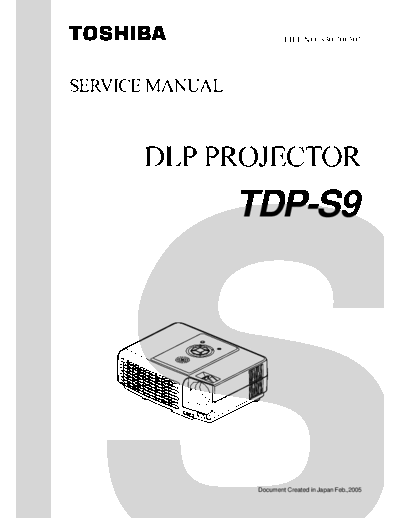
Image preview - the first page of the document

>> Download tdp-s9_174 documenatation <<
Text preview - extract from the document
                          FILE NO. 330-200502


SERVICE MANUAL


                 TDP-S9


                  Document Created in Japan Feb.,2005
                                                                                                Table of Contents

Chapter 1 System Introduction ...................................................................................... 1
          Technical Specification .................................................................................... 1
          System Block Diagram .................................................................................... 2
          Optics Conceptual Picture ............................................................................... 3

Chapter 2 Firmware Update ............................................................................................ 4
          Setup Tool / Equipment .................................................................................... 4
          Upgrading Procedure ...................................................................................... 4

Chapter 3 Machine Disassembly and Replacement ..................................................... 6
          General Information ......................................................................................... 6
          Disassemble Lamp Module ............................................................................. 7
          Disassemble Lens Cover & IO Cover .............................................................. 8
          Disassemble Top Cover and Front Cover ........................................................ 9
          Disassemble Control Panel Cover, Speaker & Key Pad Board ...................... 10
          Disassemble Main Board ............................................................................... 11
          Disassemble Ballast Module ......................................................................... 12
          Disassemble Optical Engine.......................................................................... 13
          Disassemble Power Board ............................................................................ 14
          Disassemble Power Outlet Set ...................................................................... 15
          Disassemble Foot Screw Assembly .............................................................. 16
          Exploded Overview ........................................................................................ 17

Chapter 4 Troubleshooting........................................................................................... 18
          Video Signal troubleshooting ......................................................................... 19
          Operation Function Troubleshooting .............................................................. 22
          Power Source Troubleshooting ...................................................................... 23
          Function Test and Alignment .......................................................................... 24
               Equipment Needed ............................................................................... 24
               Test Condition ....................................................................................... 24
          Test Display Modes and Patterns ................................................................... 25
               Compatible Modes ................................................................................ 25
               Function Test Display Pattern ................................................................ 26

Chapter 5 Connector Information ................................................................................ 28
          Introduction .................................................................................................... 28
          Main Board .................................................................................................... 28
          Power Board .................................................................................................. 32
          Ballast Board ................................................................................................. 33

Chapter 6 Parts List ....................................................................................................... 34
          Parts List ........................................................................................................ 34
                                                                                   Chapter 1

System Introduction
Technical Specification
                     Item                                 Description
       Display Type                0.55" DMD/DDR
       Lamp Type                   Ushio E19 200W
       Brightness                  1,400 Lumen (typical), 1,120 Lumen (minimum)
       ANSI Contrast Ratio         Typical = 200 ; Minimum = 100
       Resolution (Pixels)         800
◦ Jabse Service Manual Search 2024 ◦ Jabse Pravopis ◦ onTap.bg ◦ Other service manual resources online : Fixya ◦ eServiceinfo