Service Manuals, User Guides, Schematic Diagrams or docs for : Tektronix 7d15_sm
<< Back | HomeMost service manuals and schematics are PDF files, so You will need Adobre Acrobat Reader to view : Acrobat Download Some of the files are DjVu format. Readers and resources available here : DjVu Resources
For the compressed files, most common are zip and rar. Please, extract files with Your favorite compression software ( WinZip, WinRAR ... ) before viewing. If a document has multiple parts, You should download all, before extracting.
Good luck. Repair on Your own risk. Make sure You know what You are doing.
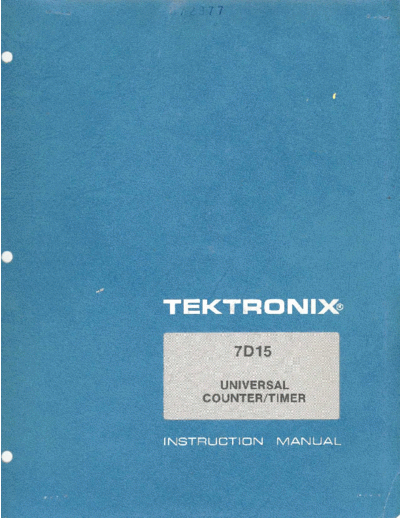
Image preview - the first page of the document

>> Download 7d15_sm documenatation <<
Text preview - extract from the document
                "
      , Frx
~ a c~~  .. .
                            TEKTRONIX
                                    7D15

                                  UNIVERSAL
                                COUNTER/TIMER


                            INSTRUCTION            MANUAL
Tektronix, Inc .
P .O . Box 500
Beaverton, Oregon   97077          Serial Number


070-1433-00                                         First Printing SEP 1974
                    WARRANTY

All TEKTRONIX instruments are warranted against
defective materials and workmanship for one year .
Any questions with respect to the warranty should
betaken up with yourTEKTRONIX Field Engineeror
representative .

All requests for repairs and- replacement parts
should be directed to the TEKTRONIX Field Office
or representative in your area . This will assure you
the fastest possible service. Please me ede the
instrument Type Number or Part Number and Seriai
Number with all requests for parts or service .

Specifications and price change priviiege~:, reserved .

Copyright     1974 by Tektronix, Inc ., Beaverton-,
Oregon . Printed in the United States of America. All
rights reserved . Contents of this publication may not
be reproduced in any form without permission of
Tektronix, Inc.

U .S .A . and foreign TEKTRONIX products covered
by U .S . and foreign patents and/or patents pending.

TEKTRONIX is a registered trademark of Tektronix,
Inc .
                TABLE OF CONTENTS
SECTION 1    SPECIFICATION                              Page
             Introduction                               1-1
             Electrical Characteristics                 1-1
             Environmental Characteristics              1-7
             Physical Characteristics                   1-7

SECTION 2    OPERATING INSTRUCTIONS
             Installation                               2-1
             Front Panel Controls and Connectors        2-2
             Modes of Operation                         2-7
             Operation and Checkout                     2-10

SECTION 3    CIRCUIT DESCRIPTION
             Introduction                               3-1
             Block Diagram Description                  3-1
                General                                 3-1
                Input                                   3-1
                Clock                                   3-1
                Gate                                    3-2
             Counters and Readout                       3-7
                Reset                                   3-7
             Trigger Input Amplifiers                   3-8
             Time Base                                  3-8
             Arm Inputs                                 3-9
             Reset Circuitry                            3-9
             Readout Theory                             3-10
                General                                 3-10
                CH 1 Column and Row Data                3-10
                CH 2 Column and Row Data                3-12
                Overflow                                3-13
             -5 V Supply                                3-14

SECTION 4    MAINTENANCE
             Introduction                               4-1
             Preventive Maintenance                     4-1
             Troubleshooting                            4-1
             Corrective Maintenance                     4-3
             Component Replacement                      4-4
             Recalibration After Repair                 4-4

SECTION 5    CALIBRATION
             Introduction                               5-1
             Test Equipment Required                    5-1
             Calibration Procedure                      5-4
             Index to Calibration Procedure             5-5

SECTION 6    ELECTRICAL PARTS LIST
             Abbreviations and Symbols

SECTION 7    DIAGRAMS AND CIRCUIT BOARD ILLUSTRATIONS
             Symbols and Reference Designators

SECTION 8    MECHANICAL PARTS LIST
CHANGE INFORMATION
Fig. 1-1 . 71315 Universal Counter/Timer .
                                                                                                                     Section 1-71315


Introduction
                                              SPECIFICATIONS
   The 71315 is a digital counter plug-in designed for use with all readout-equipped 7000-Series Oscilloscope mainframes .
It will function in any plug-in compartment ; however, in the vertical compartment, a selectable display is internally con-
nected to the oscilloscope . When used in the horizontal compartment, mainframe triggers are available to the 71315.

   The 71315 has eight modes of operation : Frequency-DC to 225 MHz direct, Frequency Ratio-0 to 10 5 :1, Period-
10 ns to 105 s, Period Averaging- 10 ps resolution, TIM- 10 ns to 105 s, TIM Averaging-1 ns accuracy, Totalize-1 to 10 8
events, Manual Stop Watch-to 10 5 s.

    The electrical specifications listed in the Performance Requirement column are valid over the stated environmental range
for instruments calibrated at an ambient temperature of +20
◦ Jabse Service Manual Search 2024 ◦ Jabse Pravopis ◦ onTap.bg ◦ Other service manual resources online : Fixya ◦ eServiceinfo