Service Manuals, User Guides, Schematic Diagrams or docs for : Tektronix DC505a

<< Back | Home

Most service manuals and schematics are PDF files, so You will need Adobre Acrobat Reader to view : Acrobat Download Some of the files are DjVu format. Readers and resources available here : DjVu Resources
For the compressed files, most common are zip and rar. Please, extract files with Your favorite compression software ( WinZip, WinRAR ... ) before viewing. If a document has multiple parts, You should download all, before extracting.
Good luck. Repair on Your own risk. Make sure You know what You are doing.


Image preview - the first page of the document
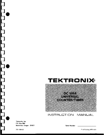
DC505a


>> Download DC505a documenatation <<

Text preview - extract from the document
                          TEKTRONIX


                          INSTRUCTION MANUAL
Tektronix, Inc .
P .Q . Box 500
Beaverton, Oregon 97077         Serial Number

O10-1984-00                                     First Printing APR 1915
                                                           DC 505A


                                              TABLE
                                        OF CONTENTS

SECTION 1   OPERATING INSTRUCTIONS                  Page

            INTRODUCTION                            1-1
              Installation                          1-1
            OPERATIONAL CHECK                       1-2
              Controls and Connectors               1-2
              Display Tests                         1-2
            INPUT CONSIDERATIONS                    1-4
              Input Sources                         1-4
              Input Coupling                        1-4
              Attenuators and Maximum Input Volts   1-4
              Sensitivity and Frequency Range       1-4
              Slope and Level                       1-4
            FREQUENCY MEASUREMENTS                  1-5
              Frequency A                           1-5
              Triggering                            1-5
              Measurement Intervals                 1-5
              Measurement Rate                       1-5
            RATIO MEASUREMENTS                       1-6
              Triggering                             1-6
              Resolution                             1-6
            PERIOD MEASUREMENTS                      1-6
              Gating                                 1-6
              Averag ing                             1-6
              Low Frequencies                        1-6
            TIME INTERVAL MEASUREMENTS               1-6
              General                                1-6
              Width B Mode                          1 -~
              Time A--B Mode
               Time Interval Averaging              1-8
               Single-Shot using HOLD               1-8
            EVENT MEASUREMENTS                      1-8
              Averag ing                            1-8
            TOTALIZING                              1-9
              Purpose                               1-9
              Operation                             1-9
            FUNCTIONS AVAILABLE AT REAR CONNECTOR   1-10
              Customizing the Interface             1-10
              Control Lines                         1-1~
              Signal Lines                          1-1~
DC 505A


TABLE OF
CONTENTS (cont)

          SECTION 1   OPERATING INSTRUCTIONS (cont)                              Page

                      ELECTRICAL CHARACTERISTICS
                        Performance Conditions                                   1-11
                        Table t-6 Channels A & B Input                           1-11
                        Table 1-7 Display Resolution and Accuracy                1-12
                        Table 1-8 Internal Time Base                             1-14
                        Table 1-9 Display                                        1-15
                        Table 1-10 Outputs                                       1-15
                        Table 1-11 Environmental                                 1-16

          SECTION 2   THEORY OF OPERATION

                      INPUT AND TRIGGER                                          2-1
                        AC/DC Selection, Attenuators, and Coupling, CH A & (B)   2-1
                        Input Amplifier, Signal Shaping, Slope Selection and
                        Output                                                   2-1
                        Signal Selection                                         2-1
                        Time A-B                                                 2-1
                      AVERAGING AND CONTROL                                      2-2
                        Averaging Divider                                        2-2
                        Gate and Control Logic Generator                         2-2
                        Phase Lock Loop                                          2-3
                      COUNTERS, DISPLAY MULTIPLEXING, TIME BASE AND
                        PARAMETER SELECTION                                      2-3
                        10


◦ Jabse Service Manual Search 2024 ◦ Jabse PravopisonTap.bg ◦ Other service manual resources online : FixyaeServiceinfo