Service Manuals, User Guides, Schematic Diagrams or docs for : Tektronix TDS7000 TekScope_Opt_App_1.0.10_071-1883-01_063-3914-10 TekScope_Opt_App_1.0.10_071-1883-01_063-3914-10 Documents RT-EYE_Documentation OptSSTQuickReference

<< Back | Home

Most service manuals and schematics are PDF files, so You will need Adobre Acrobat Reader to view : Acrobat Download Some of the files are DjVu format. Readers and resources available here : DjVu Resources
For the compressed files, most common are zip and rar. Please, extract files with Your favorite compression software ( WinZip, WinRAR ... ) before viewing. If a document has multiple parts, You should download all, before extracting.
Good luck. Repair on Your own risk. Make sure You know what You are doing.


Image preview - the first page of the document
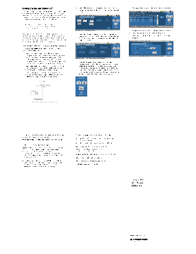
OptSSTQuickReference


>> Download OptSSTQuickReference documenatation <<

Text preview - extract from the document
Getting Started with Option SST                                 4. Select Measurement> Configure. Select the Source tab.      7. The application displays results for the measurement.
                                                                    Set the Test Method to BIST FIS/User. Set the channel
You can use this side of the Quick Reference to start to take       to Ch1.
measurements with the Option SST Serial ATA and Serial
Attached SCSI Analysis modules that plug into the RT-Eye
Compliance and Analysis Solution. The other side contains
a complete menu tree for Option SST software.

    NOTE. For complete operating instructions
    and General Safety information, refer to the
    online help for the application.
                                                                                                                              8. To generate a report, select Utilities> Report Generator.
                                                                                                                              9. Select the template in the Generate Report tab.
The Option SST Serial ATA and Serial Attached SCSI              5. Select the General Config tab. Set the Usage Model as
Analysis modules transform a digital oscilloscope into an           appropriate, Device Type to Drive, and set the Number     10. Select the Generate button to post the test data to the
analysis tool to test storage devices according to the Serial       of UI and Cable Attn as appropriate. Set the Diff Volt        template.
Advanced Technology Attachment or SATA (Gen I and Gen               Option to Option1.
II) and Serial Attached SCSI (SAS) standards.

Performing a Differential Output Voltage Measurement
To measure the differential output voltage of a Serial ATA
device, follow these steps:
1. Select File> Run Application> RT-Eye Serial
   Compliance and Analysis from the oscilloscope menu
   bar. (For supported B-series oscilloscopes, on the
   oscilloscope menu bar, click App> RT-Eye Serial
   Compliance and Analysis. For DPO oscilloscopes, select       6. Push the "Running Man" button to start taking
   Analyze> RT-Eye Serial Compliance and Analysis.)                 measurements. Follow the on-screen prompts to input
2. Select Measurements> Serial ATA. Set the Test Point to           different test patterns to complete the measurement.
   Transmitter, the Probe Type to Differential, and the             When the measurement is completed successfully, the
   measurement to Differential Output Voltage.                      application automatically displays the results. You can
3. Connect the probes to the device under test. For                 also view the results by selecting Results> Summary or
   example, the test setup using a differential probe for           Results> Details from the application menu bar.
   Differential Output Voltage is shown below.


For up-to-date information on Tektronix oscilloscope            To order an upgrade for an existing oscilloscope:
solutions for Serial ATA, access the
                                                                H Opt. RTE: RT-Eye Serial Data Compliance and
www.tektronix.com/Measurement/scopes/Web page.
                                                                  Analysis Software
                                                                H Opt. J3- Jitter and Timing Analysis Software
Option SST Ordering Information
                                                                Recommended Products and Accessories
Supports the TDS6804B, TDS6604/B, TDS7704B, and
DPO/DSA70000 series oscilloscopes; refer to the Optional        Arbitrary Waveform Generator: AWG
Applications Software on Windows-Based Oscilloscopes            610/615/710/710B/715B
Installation Manual for a complete list of supported
models. The applications CD includes a PDF file of the          High Bandwidth Differential Probe: P7380, P7380SMA
installation manual.                                            SMA Cables: Tektronix part number 174-1427 -00
If you order the Option SST along with a TDS6804B,              SMA Attenuators: Tektronix part number 015-1002 -01
TDS6604/B, TDS7704B series oscilloscope, the Option
SST Serial ATA and Serial Attached SCSI Analysis                TDR Measurement: TDS8200/80E04
Software will already be installed and enabled.


                                                                                                                                 Option SST
                                                                                                                                 Test Solution
                                                                                                                                 Reference


                                                                                                                               www.tektronix.com

                                                                                                                               *P071195601*
                                                                                                                               071-1956-01
Option SST Menu Tree

                         Recall Default
                         Recall
                         Save                       Do not override the setup in BIST FIS/User method
            File         Recall Recent
                                                    Prompt for correct waveform confirmation during run
                         Preferences
                         Minimize                   Refine filter initial condition for SATA AC CM
                         Exit                       Overcome the filter transient response by discarding the fixed time constants of data

                                                                                  Single Ended
        Modules          Serial ATA                 Probe Type                    Differential
                         SAS

                                                    Test Point                    Transmitter
                                                                                  Receiver                                                                      Timing: Eye, Bit Rate, Differential Skew*, Rise
                                                    Device ID                                                                                                   and Fall Time, Unit Interval , Select All
                                                                                  Eye                                                                           Amplitude: Differential Output Voltage
                                                    Description                   Bit Rate                                                                      AC CM Voltage*
                        Select                                                    Differential Skew*
                                                    Timing
                                                                                  Rise and Fall Time
                                                                                  Unit Interval
                                                                                  Select All

                                                                                   Differential Output Voltage
                                                    Amplitude
                                                                                   AC CM Voltage*

                                                    OOB**: COMWAKE, COMINIT, COMRESET

                                                                                  Test Method                         AWG | BIST FIS/User

                                                                                  Live                                Ch1Ch3 | Ch1Ch4 | Ch2Ch3 | Ch2Ch4

                                                                                  Trigger                             Ch1 | Chf2 | Chf3 | Ch4
                                                    Source
                                                                                  Ref                                 Ref1Ref2 | Ref1Ref3 | Ref1Ref4 | Ref2Ref3 | Ref2Ref4 | Ref3Ref1 | Ref3Ref2

                                                                                  File                                File Browser
   Measurements
                                                                                   Usage Model                        Gen1i | Gen1x | Gen1m | Gen2i | Gen2x | Gen2m
                         Configure
                                                                                   Device Type                        Host | Drive
                                                    General Config
                                                                                  Cable Attn

                                                                                   OOB Type                           In Spec | Out of Spec | Inter Burst
                                                                                   Num of UI
                                                                                   Diff Volt Option                   Option1 | Option2

                                                                                                                      Window Size
                                                                                  Clock Recovery
                                                                                                                      Scan Incr
                                                    Clock Config
                                                                                                                      Method                    Const Clk: Mean | Const Clk: Median
                                                                                  Analysis Window
                                                                                                                      250 UI | 5 UI

                                                                                  Transition and Nontransition Bits
                                                    Plot Config
                                                                                  All Bits

                         Limits                     Limits File File Browser


                         Summary
         Results         Details
                                                                                  New
                         Worst Case Eye
                                                                                  Edit Template File Browser
                                                    Define Test Template          Edit
        Utilities       Report Generator***
                                                                                  New
                                                    Define Report Layout          Edit Template File Browser
                         Help Topics
          Help                                                                    Edit
                         PDF Help
                         About RTEYE                                              New
                                                     Generate Report              Edit Template File Browser
                                                                                  Edit


         * Added when the Probe Type is Single ended.
        ** Added only when the Test Point is Transmitter.
      *** The Report Generator utility includes online help specific to the use of the Report Generator Editor.


Copyright  Tektronix, Inc.


◦ Jabse Service Manual Search 2026 ◦ Jabse PravopisonTap.bg ◦ Other service manual resources online : FixyaeServiceinfo