Service Manuals, User Guides, Schematic Diagrams or docs for : Tektronix TDS7000 TekScope_Opt_App_1.0.10_071-1883-01_063-3914-10 TekScope_Opt_App_1.0.10_071-1883-01_063-3914-10 Documents TDSVNMQuickReference

<< Back | Home

Most service manuals and schematics are PDF files, so You will need Adobre Acrobat Reader to view : Acrobat Download Some of the files are DjVu format. Readers and resources available here : DjVu Resources
For the compressed files, most common are zip and rar. Please, extract files with Your favorite compression software ( WinZip, WinRAR ... ) before viewing. If a document has multiple parts, You should download all, before extracting.
Good luck. Repair on Your own risk. Make sure You know what You are doing.


Image preview - the first page of the document
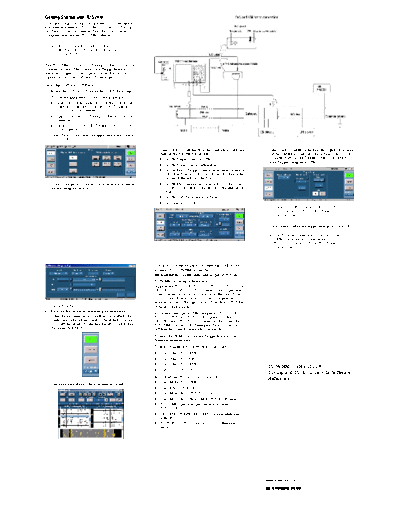
TDSVNMQuickReference


>> Download TDSVNMQuickReference documenatation <<

Text preview - extract from the document
Getting Started with TDSVNM
You can use this side of the quick reference to start taking
measurements with the TDSVNM CAN and LIN Timing
and Protocol Decode software. The other side contains a
complete menu tree for TDSVNM software.

    NOTE. For complete operating instructions
    and general safety information, refer to the
    online help for the application.


The TDSVNM CAN and LIN Timing and Protocol Decode
software and the ATM-1 Automotive Trigger Module
transform a digital oscilloscope into an analysis tool to
capture and decocde CAN and LIN messages.

Decoding CAN and LIN Protocols
To decode the CAN and LIN messages, follow these steps:
1. To start the application, do one of the following:
   H Select File > Run Application > in the oscilloscope
      menu bar. Then select CAN and LIN Timing and
      Protocol Decode Software
   H App > CAN and LIN Timing and Protocol Decode
      Software
   H Analyze > CAN and LIN Timing and Protocol De-
      code Software
2. Select Tests > Select from the application menu. Select
   CAN & LIN.

                                                                4. Select Tests > Configure from the application menu, and        5. Select Tests > Trigger Setup from the Application menu.
                                                                    then set the following parameters:                                Set the Trigger-In source and the Sample Point Location
                                                                    H Set the Trigger Using to ATM-1.                                 as appriopriate. Set the Trigger Event to Elementary
                                                                                                                                      with Trigger Using set to ATM-1.
                                                                    H Set the Probe Type to Differential.
                                                                    H Set the Bus 1 (Trigger Source) parameters: Source to
                                                                       Ch1, Bus Type to CAN-DW-LH, and Bit Rate to the
                                                                       bit rate of the selected bus type.
3. Connect the probes to the device under test as shown in          H Set the Bus 2 parameters: Source to Ch2, Bus Type
    the following illustration.                                        to LIN, and Bit Rate to the bit rate of the selected bus
                                                                       type.
                                                                    H Set the CAN Node Sensor to None.
                                                                    H Set Analysis to Data.
                                                                                                                                      NOTE. DPO-CAN is available only on DPO
                                                                                                                                      oscilloscopes when CB:CANBus Trigger
                                                                                                                                      option is enabled.

                                                                                                                                  6. Click Define. Define the trigger settings and click OK.

                                                                                                                                      NOTE. To define trigger events, you must have
                                                                                                                                      the ATM-1 Automotive Trigger Module or the
                                                                                                                                      DPO oscilloscope with CB:CANBus Trigger
                                                                                                                                      option enabled


                                                                For up-to-date information on Tektronix oscilloscope
                                                                solutions for TDSVNM, access the
                                                                www.tektronix.com/Measurement/scopes/ Web page.
                                                                TDSVNM Ordering Information
                                                                Supports the TDS5000B, TDS7054, TDS7104, TDS7000B,
                                                                DPO7000, and DPO/DSA70000 series oscilloscopes; refer
                                                                to the Optional Applications Software on Windows-Based
                                                                Oscilloscopes Installation Manual for a complete list of
                                                                supported models. The applications CD includes a PDF file
7. Set ACK to No.                                               of the installation manual.
8. Push the Run button to start taking measurements.            If you order the Option VNM along with a TDS5000B,
    When the measurement is completed successfully, the         TDS7054, TDS7104, TDS7000B; Option LSA for
    application automatically displays the results. You can     DPO7000 and DPO/DSA70000 series oscilloscopes, the
    also view the results by selecting Results > Details from   TDSVNM CAN and LIN Timing and Protocol Decode
    the application menu bar.                                   Software will already be installed and enabled.
                                                                To order the ATM-1 Automotive Trigger Module, contact a
                                                                Tektronix representative.
                                                                To order an upgrade for an existing oscilloscope:
                                                                H   Opt. VNM - TDS5BUP
                                                                H   Opt. VNM - TDS7UP
                                                                H   Opt. VNM - TDS7BUP
                                                                                                                                     TDSVNM CAN and LIN
                                                                H   Opt. LSA - DPO7UP
                                                                                                                                     Timing and Protocol Decode Software
                                                                Recommended Products and Accessories
                                                                                                                                     Reference
9. The application displays the measurement results.            H Opt. 3M for TDS5000B
                                                                H Opt. 18 for TDS5000B
                                                                H Opt. 2M or 3M for TDS7054/7104
                                                                H Opt. 2M or 3M or 4M or 5M for TDS7000B series
                                                                H TCA-1MEG probe adapter, while using with
                                                                   TDS7000B
                                                                H TPA-BNC, TEKPROBEt BNC Adapter while using
                                                                   with DPO7000
                                                                H P5205, P5210, P5200 and ADA400A differential
                                                                   probes


                                                                                                                                   www.tektronix.com

                                                                                                                                   *P071188002*
                                                                                                                                   071-1880-02
TDSVNM Menu Tree

                       Recall Default          Math Destination for    Bus1 Source
                                                                       Bus2 Source                        Math1 | Math2 | Math3 | Math4
                       Recall                  Single-ended probes
                       Save                                            CAN Node Sensor Source
        File           Recall Recent                                   Bus1 Source
                       Preferences                                                                        Units | Mid | Hysteresis
                                               Reference Level         Bus2 Source
                       Minimize
                       Exit                                            CAN Node Sensor Source             Slope | Units | Mid | Hysteresis
                                               Do Autoset Every Time
                                                                       CAN
                                               CAN and LIN             LIN
                                               Protocol Decoding       CAN & LIN

                      Select                                                                                                                     Timing: Eye, Bit Rate, Differential Skew*, Rise
                                                                       Oscillator Tolerance
                                                                                                                                                 and Fall Time, Unit Interval , Select All
                                                                       Eye Diagram
                                                                                                                                                 Amplitude: Differential Output Voltage
                                               Timing Analysis Tests   Bus Traffic
                                                                                                                                                 AC CM Voltage*
                                                                       Data Rate
                                                                       Wakeup Time
                                                                       Propagation Delay


                                                Trigger Using          DPO-CAN | ATM-1 | Standard

                                                Probe Type             Single-ended | Differential

                                                                       Source                             Ch1 | Ch2 | Ch3 | Ch4 | Ref1 | Ref2 | Ref3 | Ref4 *
                                                                                                          Ch1Ch2 | Ch3Ch4 | Ch1Ch3 | Ch2Ch4 | Ref1 | Ref2 | Ref3 | Ref4 **
                                                Bus1 (Trigger          Bus Type
                                                Source)                                                   CAN-DW-HL | CAN-DW-LH | CAN-SW | CAN-FT-HL | CAN-FT-LH | LIN
                                                                       Bit Rate

                       Configure                                                                          Ch1 | Ch2 | Ch3 | Ch4 | Ref1| Ref2 | Ref3 | Ref4 | None*
                                                                       Source                             Ch1Ch2 | Ch3Ch4 | Ch1Ch3 | Ch2Ch4 | Ref1 | Ref2 | Ref3| Ref4 | None**
                                                Bus2
                                                                       Bus Type                           CAN-DW-HL | CAN-DW-LH | CAN-SW | CAN-FT-HL | CAN-FT-LH | LIN | None
                                                                       Bit Rate
         Tests
                                                                                                          Ch1 | Ch2 | Ch3 | Ch4 | Ref1| Ref2 | Ref3 | Ref4 | None*
                                                CAN Node Sensor        Source
                                                                                                          Ch1Ch2 | Ch3Ch4 | Ch1Ch3 | Ch2Ch4 | Ref1 | Ref2 | Ref3| Ref4 | None**
                                                                       ID
                                                Analysis               Data | Timing


                                               Trigger-In Source       Aux In | Ch1 | Ch2 | Ch3 | Ch4


                                                Sample Point           Location


                                                                                                          Elementary | Logical | Advanced
                                                                       Select
                                                                                                          Define
                       Trigger Setup           Trigger Event{
                       (ATM-1)
                                                                       Input ID
                                                                                                           Settling Latency Time
                                               Trigger Setup}          Wakeup Time                         Trigger Level
                                                                                                           Trigger Slope
                                                ACK                    No
                                                                       Yes

                                                Trigger On             CAN Message | Frame | ID | Data | ID and Data | EOF | Missing ACK

                                                CAN Type               Standard | Extended
                        Trigger Setup
                        (DPO-CAN)              Type of Frame           Data | Remote | Error | Overload

                                                Format                 Binary | Hexadecimal

                                               Data Direction          Either | Write | Read

                         Connect


        Results        Details


        Utilities      ATM-1 License Installation


        Help            Help Topics
                        About TDSVNM
                        About ATM-1


         * Displayed when the Probe Type is Differential.
        ** Displayed when the Probe Type is Single-ended.
         { Available only for protocol decoding.
         } Available only for Wakeup Time test.


Copyright  Tektronix, Inc.


◦ Jabse Service Manual Search 2026 ◦ Jabse PravopisonTap.bg ◦ Other service manual resources online : FixyaeServiceinfo