Service Manuals, User Guides, Schematic Diagrams or docs for : Tektronix TEK 2754 Service Vol1 Part1
<< Back | HomeMost service manuals and schematics are PDF files, so You will need Adobre Acrobat Reader to view : Acrobat Download Some of the files are DjVu format. Readers and resources available here : DjVu Resources
For the compressed files, most common are zip and rar. Please, extract files with Your favorite compression software ( WinZip, WinRAR ... ) before viewing. If a document has multiple parts, You should download all, before extracting.
Good luck. Repair on Your own risk. Make sure You know what You are doing.
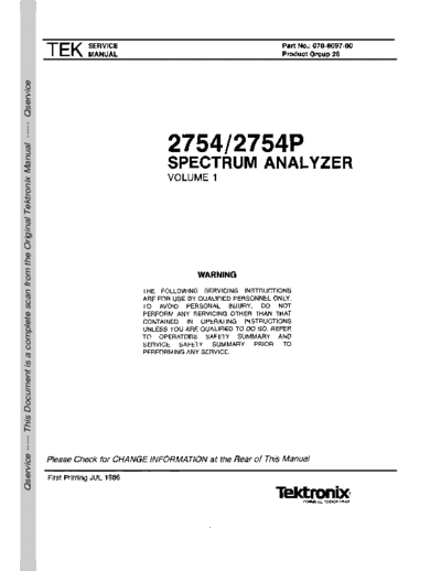
Image preview - the first page of the document
>> Download TEK 2754 Service Vol1 Part1 documenatation <<
Text preview - extract from the document
Qservice ----- This Document is a complete scan from the Original Tektronix Manual ----- Qservice
Copyright @ 1986 Tektronix, Inc. All rights reserved.
Contents of this publication may not be reproduced i n
any form without the written permission of Tektronix, Inc.
Products of Tektronix, Inc. and its subsidiaries are
covered by U.S. and foreign patents and/or pending
patents.
TEKTRONIX, TEK, SCOPE-MOBILE, and are
registered trademarks of Tektronix, Inc. TELEQUIP-
MENT is a registered trademark of Tektronix U.K.
Limited.
Printed i n U.S.A. Specification and price change
privileges are reserved.
Tektronix, Inc.
P.O. Box 500
Beaverton, Oregon 97077 Serial Number
275412754P Service Vol. 1
PREFACE
This manual contains service information for the ANSI Y1.l - Abbreviations
TEKTRONIX 275412754P. The information is located in
ANSl Y32.2 - Graphic Symbols
two volumes. Volume 1 contains the text and Volume 2
contains the diagrams and parts lists. The Table of IEEE 91 - Logic Symbols
Contents in each volume lists the contents of both
volumes. Change/History Information
Manuals that describe other aspects of the product Sometimes instrument changes occur or manual
are: errors are found that make some of the information in
Operator's Manual the manual inaccurate. When that happens, Manual
Change lnformation notices are inserted at the rear of
Operator's Handbook the manual. This helps ensure that the manual contains
Programmer's Manual the latest and most accurate information available when
the product is sold.
Who Should Use This Manual? History information, with the updated data, is
This manual is intended for electronic technicians integrated into the text or diagrams. When a text page
is updated, the revised pages are identified by a revi-
with experience in servicing digital, analog, and rf circu-
sion date in the lower inside corner of the page. When
itry. Circuit analysis is mostly functional and should
a diagram is updated, the revision date is placed at the
help isolate most malfunctions to a board or block of
lower center of the diagram. History information is
circuitry. The technician should then be able, with the
shown with a gray tint. When a component value is
aid of test equipment, to isolate the malfunction to a
changed, the designator on the drawing is boxed with a
specific component or components.
grey outline. When a circuit is deleted or changed, the
This instrument contains firmware that provides a original configuration is shown in grey, drawn either at
thorough instrument check during power up and during its original location or to the side of the drawing.
operation, and if needed, guides the user through an
If you have a manual other than the one that came
abbreviated front-panel calibration procedure. If cali-
with your instrument it may contain revisions that do not
bration cannot be achieved, a diagnostic test detects
and isolates most problems to the system, such as 1st apply to your instrument; however all history informa-
tion that pertains to the earlier instruments is retained.
LO. The technician can then run troubleshooting diag-
When a major modification has been made to an
nostics to further isolate the problem to the board or
assembly or circuit board, the data for the replaced
block of components. Refer to the Maintenance section
assembly will follow the new information and will be
for diagnostics information.
identified with appropriate titles or headinqs such as
instrument seriai .number range or the assembly or
Documentation Standards board part numbers.
Most terminology and graphics follow ANSl stan- Also, if your instrument has an assembly replaced
dards. A glossary of terms is provided as an appendix.
with a newer version, documentation for the newer
Refer to the following standards:
assembly may be supplied. Contact any Tektronix Ser-
vice Center for information.
2754/2754P Service Vol. 1
TABLE OF CONTENTS
The 2754 Service Manual is divided into two volumes .
VOLUME 1
Page Page
PREFACE ........................... .
.............................. i Section 4 PERFORMANCE CHECK
TABLE OF CONTENTS ........................ . ............... ii Introduction .............................. . . . . 4-1
. .
LIST OF ILLUSTRATIONS ....................................... ix
Incoming Inspection Test ...................... 4-1
LIST OF TABLES .....................................................xii
Verification of
SAFETY SUMMARY ............................. . ...............xiii Tolerance Values .................... ..
.. ...... 4-1
History Information ................................ 4-1
Equipment Required .............................. 4-1
Section 1 GENERAL INFORMATION
Firmware Version .................................. 4-3
Product Description ................... . 1-1. .....
. Error Message Readout ........................ 4-3
Conformance to Initial Power-Up ............................ .... 4-4
Industry Standards ................... . 1-1. .....
. Calibrate Position.
Product Service .................................... 1-1 Center Frequency.
Instrument Construction ........................1-2 Reference Level.
Installation and and Dynamic Range .............................. 4-5
Preparation for Use ........................ . 1-2 PERFORMANCE CHECK
Changing Power Input Range ................ 1-2 PROCEDURE ...................... .
.. ......... 4-6
Replacing Fuses ................................... 1-2 1. Check Center Frequency
Selected Components ...........................1-2 Accuracy .............................................. 4-6
Assembly and 2. Check Residual FM ..........................4-8
Circuit Numbering ......................... . 1-2
. .... 3 . Check Frequency
Power-up Messages ..............................1-3 Span/Div Accuracy ................................4-9
Options .................................................. 1-3 4. Check Sweep Time
Accessories ........................... . ........... 1-3 Accuracy ............................................ 4-11
5. Check Pulse Stretcher ......................4-12
6. Check Resolution Bandwidth
Section 2 SPECIFICATION and Shape Factor ................................. 4-12
7. Check Calibrator
ELECTRICAL ..................................... 2-1
Output ................................................ 4-12
Verification of Tolerance Values ....... 2-1
8. Check Noise Sidebands ...................4-13
Frequency Related Characteristics ... 2-1
9. Check Frequency
Amplitude Related Characteristics .... 2-7
Response ..............................................4-13
Input Signal Characteristics .............. 2-12
10. Check Display Dynamic
Output Signal Characteristics ........... 2-15
Range and Accuracy .............................4-17
Power Requirements ........................2-16
11. Check Preselector
General Characteristics .................... 2-17
Ultimate Rejection ................................. 4-18
12. Check RF Attenuator Accuracy
ENVIRONMENTAL .................................2-18
(0 to 60 dB in 10 dB Steps) ...................4-18
PHYSICAL ............................................ 2-19
13. Check IF Gain
Accuracy ............................................. 4-22
14. Check Gain Variation Between
Section 3 INSTALLATION
Resolution Bandwidths .......................... 4-23
UNPACKING AND 15. Check Sensitivity ............................4-24
INITIAL INSPECTION ............................ 3-1 16. Check Residual
CONNECTING POWER ....................... 3-2 Spurious Response ............................... 4-25
Power Source and 17. Check lntermodulation
Power Requirements ........................ 3-2 Distortion ................... .
. ................ 4-25
STORAGE AND REPACKAGING ........... 3-2
Storage ............................................3-2
Repackaging for Shipment ................ 3-3
iii
2754/2754P Service Vol 1 .
TABLE OF CONTENTS (Cont.)
Page Page
Section 4 PERFORMANCE CHECK (Cont.) Section 6 MAINTENANCE
18. Check Harmonic INTRODUCTION ............................... 6-1
Distortion ............................................... 4-26 Removing the
19. Check LO Emission ........................ 4-27 Instrument from its Cabinet .......... 6-1
20. Check 1 dB Static-Sensitive Components ....... 6-1
Compression Point ................................ 4-29 PREVENTIVE MAINTENANCE ............... 6-3
21. Check Triggering Operation Elapsed Time Meter ..................... 6-3
and Sensitivity ...................................... 4-29 Cleaning ........................ ............
. 6-3
22. Check External Lubrication ................... .
. .... 6-3
Sweep Operation ...................................4-30 Fixtures and Tools
23. Check VERT OUTPUT for Maintenance ...........................6-3
Signal .................................................... 4-30 Visual Inspection .......................... 6-3
24 . Check HORlZ OUTPUT Transistor and Integrated
Signal Level ........................................... 4-31 Circuit Checks ..............................6-3
GPlB VERIFICATION PROGRAM .......... 4-32 Performance Checks
and Recalibration .........................6-4
Saving Stored Data in
Section 5 ADJUSTMENT PROCEDURE Battery-Backup Memory ...............
6-4
Introduction ........................................... 5-1
TROUBLESHOOTING ..........:
.............. 6-4
Equipment Required .......................... 5-1 . Troubleshooting Aids ...................
6-4
Preparation ............................................ 5-2
Diagrams .................................
6-4
Circuit Board
1. Adjust Low Voltage Power Supply .... 5-3 Illustrations and Component
2. Adjust Z-Axis and Locator Charts .........................6-5
High Voltage Circuits ............................. 5-5 Diagnostics ......................... 6-5
3 . Adjust Deflection Amplifier General Troubleshooting
Gain and Frequency Response ............. 5-6 .
.
Techniques .................... ........... 6-5
4. Adjust Digital Storage Calibration ..... 5-8 Semiconductor Checks ............ 6-5
5. Adjust Sweep Timing ......................... 5-10 Diode Checks ....................... 6-5 ..
.
6. Adjust Frequency Control System ..... 5-11 Diagnostic Firmware ....................
6-6
.
7 Adjust Start (0 Hz) Response Troubleshooting Steps ................. 6-6
Amplitude and Mixer Bias .....................
5-12
DIAGNOSTICS .................................... 6-6
8. Adjust 1st Converter Bias ^A 5-12 TROUBLESHOOTING USING
9. Adjust Log Amplifier .......................... 5-13 THE ERROR MESSAGE DISPLAY ....
6-6
10. Adjust Resolution Bandwidth Introduction ....................... . .
..... 6-6
and Shape Factor .................... . . .
.... 5-1 6 Combination of Error Messages 6-7 ...
11. Preset the Variable Resolution TRACE MODES ................................
6-15
Gain and Band Leveling ........................
5-18
Alternate Frequency Display ........
6-15
12. Adjust Calibrator Output Level ........ 5-20 Auxiliary Synthesizer Control ....... 6-15
13. Adjust IF Gain ................................ 5-21 Correction DisableIEnable ............
6-15
14. Adjust B-SAVE A CORRECTIVE MAINTENANCE ..............
6-16
Reference Level .......................
... ........ 5-22 Handling Static Sensitive
.
15 Adjust Preselector Driver Components ................................. 6-16
.
(Opt 01 only) ......................... . .
........ 5-22 Obtaining Replacement Parts ....... 6-16
.
16 Adjust Band Leveling for Parts Repair and Return Program 6-16
Coaxial Bands (1-5) ....................
.... 5-24
Firmware Version and
17. Phase Lock Calibration ....................
5-26 Error Message Readout ...............6-16
Selected components .................. 6-16
Replacing EPROM
or ROM Devices ................... ........ 6-16
Surface-Mounted Components .....
6-17
Replacing Surface-Mounted
Components ................................. 6-18
275412754P Service Vol 1 .
TABLE OF CONTENTS (Cont.)
Page Page
Section 6 MAINTENANCE (Cont.) Power-up Self Test ...................... 6-45
Microcomputer System Test ........ 6-45
Transistor and Integrated
Address Bus Test .........................6-47
Circuit Configurations ................... 6-18
Microcomputer Bus .................6-47
Diode Color Code ....................... 6-18
Memory Address Decoders ..... 6-48
Multiple Terminal
Processor Address Decoder .... 6-49
(Harmonica) Connectors ...............6-19
GPlB Board Address Decoders 6-49
Resistor Values ............................6-19
Clocks and Control Lines ......... 6-49
Capacitor Marking ...................... 6-19
Instrument Bus Test .....................6-49
Soldering Techniques ...................6-1 9
TROUBLESHOOTING ON THE
Replacing the Square Pin for
INSTRUMENT BUS .......................... 6-50
the Multi-pin Connectors .............. 6-19
Instrument Bus Data Transfers .... 6-50
Servicing the VR Module .............. 6-20
Instrument Bus Registers ............. 6-51
REPLACING ASSEMBLIES
Front-Panel Registers .................. 6-59
AND SUBASSEMBLIES ....................6-20
PROGRAM FOR MOVING STORED
Removing and Installing
DATA FROM THE SPECTRUM
the GPlB Board ............................ 6-20
ANALYZER TO TAPE AND
Removing or Replacing
RETURNING IT TO MEMORY ...............6-60
Semi-rigid Coaxial Cables ............ 6-23
Replacing the Dual Diode
Assembly in the 1st Mixer ............ 6-23
Section 7 THEORY OF OPERATION
Replacing the Crt .........................6-23
Repairing the Crt FUNCTIONAL AND
Trace Rotation Coil ......................6-24 GENERAL DESCRIPTION .....................7-1
Front Panel Assembly Removal ... 6-24 What It Does ........................... 7-1
Front-Panel Board Removal ......... 6-24 How It Works .......................... 7-1
Replacing Front Panel First. Second. and
Pushbutton Switches ....................6-25 Third Converters ......................7-1
Main Power Supply IF Section .................... .......... 7-2
Module Removal ...........................6-25 Display Section ........................7-2
High Voltage Power Supply .......... 6-25 Frequency Control Section ...... 7-2
Removing and Replacing the Counter and
1st LO (YIG Oscillator) ................. 6-25 Phase Lock Section ................. 7-2
Replacing the 1st (YIG) Local Digital Control Section .............7-2
Oscillator Interface Board ............ 6-26 Power Supply Section ..............7-3
Fan Assembly Removal ................ 6-26 Other Sections .........................7-3
MAINTENANCE ADJUSTMENTS ...... 6-27 DETAILED DESCRIPTION .....................7-4
2072 MHz 2nd Converter ............. 6-27 1ST CONVERTER SECTION .............7-4
Four Cavity Filter ..................... 6-27 RF Interface Circuits ....................7-4
. .
. .
Mixer ................... ..... ..... 6-27 1st Converter ................................ 7-4
110 MHz Three Cavity Filter ......... 6-29 RF Input ................................. 7-4
829 MHz Converter Maintenance . 6-30 Preselector Circuits
Troubleshooting and Calibrating (Opt . 01 Only) .................... . 7-4
the 2182 MHz 2nd LO ..................6-33 .
.
1st Mixer ...................... ....... 7-5
Preparing the 2nd L.O. 1st Local Oscillator ..................7-5
Assembly for Adjustment .............6-36 Power Divider .......................... 7-5
Reassembling the Directional Filter ....................... 7-5
2nd LO Assembly .........................6-39 2072 MHz IF Filters .................7-5
Troubleshooting and Calibrating Diplexer and Filter ...................7-5
the 16-20 MHz Phase Lock Section 6-39 2ND CONVERTER SECTION ............7-6
Troubleshooting Aids for the 2072 MHz 2ND CONVERTER ....... 7-7
2182 MHz Phase Locked Four-Cavity Filter .....................7-7
2nd LO Assembly ......................... 6-43 Mixer Circuit ............................7-7
MICROCOMPUTER SYSTEM Precision External Cables ........ 7-8
MAINTENANCE ..................................... 6-45
Memory Board Option Switch ...... 6-45
275412754P Service Vol 1 .
TABLE OF CONTENTS (Cont.)
Page Page
Section 7 THEORY OF OPERATION (Cont.) Digital Control Circuit ...............7-31
VIDEO PROCESSOR ....................7-31
Filter-to-Mixer lnterface with 1405 TV
RF Input Cable ....................7-9 Sideband Adapter ....................7-31
2nd LO-to-Mixer Video Marker ........................... 7-32
LO Input Cable ....................7-9 Video Leveling .........................7-33
2182 MHz PHASE LOCKED Video Leveler Circuits ..............7-33
.
.
2ND LO ....................... ............... 7-9 Video Filter Circuits .................7-33
2182 MHz Microstrip Video Blanking .........................7-35
Oscillator .............................. 7-9
. DIGITAL STORAGE 7-35
2200 MHz Reference Vertical Section ........................ 7-36
Board ............................ . .....7-10
..... Digitizing Circuits ................7-39
2200 MHz Reference Address Decoding ...............7-39
Mixer ...................................... 7-10 Interface Logic ....................7-39
16-20 MHz Phaselock Maximum Hold ....................7-39
Board .......................................7-10 Constant Circuit ..................7-39
829 MHz 2ND CONVERTER ......... 7-12 Output Circuits ....................7-40
IF Section .....................
..... 7-12 PeakIAverage Level
829 MHz Diplexer ................ 7-12 Circuits ........................... .....7-40
829 MHz Amplifier ............... 7-12 Horizontal Section ...................7-40
829 MHz 2nd Converter ...... 7-13 Marker IC ............................ 7-42
110 MHz IF Select ...............7-14 Tracking Digital-to-
LO Section .........................
.. 7-15 Analog Converter ................7-42
Phase Lock Circuit .............. 7-15 Update Marker Circuits .......7-42
2nd Local Oscillator Fast Retrace Blanking ......... 7-43
Ouput Circuit .......................7-17 Memories ............................ 7-43
719 MHz Output Circuit ....... 7-17 DEFLECTION AMPLIFIERS .......... 7-43
3RD CONVERTER SECTION ............ 7-18 Horizontal Section ...................7-43
110 MHz IF AMPLIFIER ...............7-18 Vertical Section ........................7-44
110 MHz BAND-PASS Z-AXIS AND RF INTERFACE ....... 7-44
FILTER ........................... . 7-19 RF Interface Circuits ................7-45
3rd CONVERTER ..........................7-19 2-Axis Circuits .........................
7-45
100 MHz Oscillator ..................7-19 Power-Fail Detector .................7-46
Mixer ................... .
.. ............ 7-19 Power Supply Monitor .............7-46
Distribution Amplifier ............... 7-19 Timer ..................................... 7-46
Calibrator ............................... 7-20 HIGH-VOLTAGE SUPPLY .............7-46
IF SECTION ......................................7-21 High-Voltage Oscillator ............
7-46
VARIABLE RESOLUTION .............7-21 Voltage Doubler ...................
7-46
VR Input ...................................7-21 High-Voltage Regulator ............
7-46
1st Filter Select ....................... 7-21 2-Axis Clipper ......................... 7-47
10 dB Gain Steps ................... 7-22 .. CRT READOUT .......................... 7-47
20 dB Gain Steps .....................7-23 Generating Readout .................7-47
Band Leveling Circuit ...............7-23 Readout On/Off Timing .......
7-47
Digital Control Circuits ............. 7-24 Character Scan ................... 7-47
+5 V Regulator Circuit ............. 7-24 Character Generator
2nd Filter Select ....................... 7-24 Timing .............................. 7-50
Post VR Amplifier Circuit ......... 7-25 Dot Delay ............................7-50
LOG AMP and DETECTOR .......... 7-25 Instrument Bus Interface ......... 7-52
Log Amplifier Circuits .............. 7-26 Control Port .........................7-52
Detector Circuit ........................ 7-28 AddressIData Port .............. 7-53
DISPLAY SECTION ...........................7-29 Frequency Dot Marker .............7-53
FUNCTIONAL DESCRIPTION ....... 7-29 FREQUENCYCONTROL
VIDEO AMPLIFIER ....................... 7-29 SECTION ....................
.................. 7-56
Log Mode Circuits ................... 7-29 Sweep . .
........................ . ...... 7-56
Linear Mode Circuits ................ 7-30 Span Attenuator .......................7-56
Pulse Stretch Circuit ................ 7-30
275412754P Service Vol. 1
TABLE OF CONTENTS (Cont.)
Page Page
Section 7 THEORY OF OPERATION (Cont.) COUNTER BOARD .......................7-77
Address Decoder .....................7-77
Center Frequency Control ........ 7-56 Service Request Circuits ......... 7-77
I st LO Driver ...........................7-56 Data Buffers ............................. 7-77
Preselector Driver lnput Amplifiers and
(Opt. 0 Only) ........................... 7-56
1 Multiplexer ............................... 7-78
SWEEP ......................................... 7-56 +2" Counter .............................7-78
Digital Control ..........................7-57 2 -bit Counter ..........................
1 7-78
Sweep Generator .....................7-58 PHASE LOCK SYNTHESIZER ...... 7-78
Trigger Circuits ........................7-58 Synthesizer .............................. 7-78
Sweep Holdoff .........................7-60 Phase Lock .............................. 7-79
SPAN ATTENUATOR ...................7-60 Offset Mixer ........................7-79
Digital Control ..........................7-60 Error Amplifier ..................... 7-80
Input Section ............................7-60 Controlled Oscillator ............7-81
Digital-to-Analog Converter ..... 7-60 Strobe Driver Circuit ............7-81
Decade Attenuator ...................7-62 DIGITAL CONTROL SECTION ..........7-83
1st LO DRIVER ........................... 7-62 Microcomputer .............................7-83
Digital Control ......................... 7-63 Processor ................................ 7-83
Input Switching ........................7-63 Microprocessor ................... 7-83
Oscillator Filter Clock ................................... 7-87
Switch Driver ........................... 7-63 Microcomputer Bus ............. 7-87
Summing Amplifier ...................7-63 Address Decoder ................7-87
Oscillator Driver .......................7-64 Timer ................................... 7-87
Reference Supply ....................7-64 PIA and Instrument Bus ...... 7-87
Mixer Bias Driver .....................7-64 DMA Controller ................... 7-87
Programmable Bias ................. 7-64 Interrupt Processing ............7-88
PRESELECTOR DRIVER
(Opt. 01 Only) ...............................7-64
Memory ..................... ...............7-89
Address Decoders ..............7-89
Digital Control Circuits ............. 7-65 RAM .................................... 7-89
Oscillator Voltage Processor ... 7-65 Options ............................ .... 7-90
IF Offset ...................................7-66 ROM .................................... 7-91
Summing Amplifier ................... 7-66 ROM Banks and GPlB .............7-91
Tracking and Address Decoder ................7-91
Shaper Circuits ........................7-66 Bank Selector ...................... 7-91
Current Driver .................... 7-67 Bank ROMs ......................... 7-91
Preselector Switch Driver ........ 7-67 GPlB Switches ....................7-92
CENTER FREQUENCY GPlA ................... .
. ........ 7-92
.
CONTROL ....................................7-67 Accessories Interface .............. 7-92
Operating Modes .....................7-67 Front Panel ..............................7-92
Digital Control ..........................7-69 Potentiometers .................... 7-92
Storage Registers ...............7-70 Output Mode Shift
Digital-to-Analog Registers and LEDs ............ 7-93
Converters .......................... 7-70 Processor ............................ 7-93
Track-and-Hold Amplifier ......... 7-70 Scanning the Keyboard ....... 7-93
Write-Back Circuit ....................7-71 Scanning the FREQUENCY
-1 0 V Reference Buffer ........... 7-71 Control Coder ...................... 7-94
COUNTER and PHASE LOCK Outputting the
SECTION ............................ ..........7-72
. Correct Code .......................7-94
FUNCTIONAL DESCRIPTION ....... 7-72 Software .............................. 7-94
Phase Lock Assembly ............. 7-72 Main Scan Routine ..............7-94
Frequency Control ................... 7-73 Keyboard Check
Controlling the Subroutine ........................... 7-94
Oscillator Frequency ........... 7-73 Frequency Coder
Counting the IF .................... 7-73 Subroutine Check ................7-95
HARMONIC MIXER ...................... 7-73 Output Subroutine ...............7-95
AUXILIARY SYNTHESIZER .......... 7-74
vii
2754/2754P Service Vol 1 .
TABLE OF CONTENTS (Cont.)
Page Page
Section 7 THEORY OF OPERATION (Cont.) Section 8 OPTIONS
POWER SUPPLY ..............................7-99 Options A1-A5 Power Cord Options ....8-1
Line Input Circuits ........................7-99 Options M I -M5 Extended Service
Inverter Circuit ..............................7-99 and Warranty Options .......................... 8-2
.
.
Multivibrator ........................ ..... 7-100 Option 01 Internal Preselector ...............8-2
Ramp Generator ........................... 7-100 Option 07 75C2 Input ............................ 8-3
Primary Regulator ........................ 7-1 00 Options 30 and 31
Inverter Logic ............................... 7-1 00 Rackmount Options ............................. 8-5
Inverter Driver .............................. 7-101 Installation Requirements .................8-5
Output Stage ................................
7-101 Option 52 North American 220V ............
8-5
Soft Start and Primary
Over-Current Circuits ...................7-102
Rectifier-Filter Circuits Appendix A GLOSSARY
(Secondary Section) .....................7-102
+5 V Voltage
GENERAL TERMS ........................ ....
FREQUENCY TERMS .......................
Reference Supply .........................7-103
AMPLITUDE TERMS .........................
Regulator Circuits ......................... 7-103
DIGITAL STORAGE TERMS .............
+5V Over-Voltage .
Protection Circuit .......................... 7-103
Fan Drive Circuit .......................... 7-1 03
VOLUME 2
Section 9 REPLACEABLE ELECTRICAL PARTS
Section 10 DIAGRAMS
Section 11 REPLACEABLE MECHANICAL PARTS
2754/2754P Service Vol 1 .
LI ILLUSTRATION (Cont.)
Figure Page Figure Page
Test equipment setup for band 6-26 Options switch on the
leveling adjustment.......................................5-25 Memory board.......................... . ......... 6-46
..
Band leveling adjustment and 6-27 A1 5 through A1 2 in
gain diode locations ................................... 5-25 microcomputer test mode ............................ 6-48
Test equipment setup for adjusting 6-28 Four main block select outputs
the Phase Lock assembly............................5-27 of address decoder U2045...........................6-48
Phase Lock assembly adjustment 6-29 RAM select output
and test point locations ................................ 5-28 in relation to OXXX........................... ... 6-48
.
6-30 I/O and S1050 select lines
Surface-mounted component in relation to OXXX........................................
6-49
lead configurations ................................... 6-17 6-31 Chip selects YO. Y1. Y5.
Diode polarity markings ...............................6-18 and Y7 in relation to I/O ............................. 6-49
Multipin (harmonica) connectors ..................6-19 6-32 Chip selects Y2. Y4. and Y6
Servicing the VR assembly........................... 6-20 in relation to I/O .................... .
. ................6-49
.
Top deck assemblies ................................... 6-21 6-33 Instrument bus check ................................. 6-50
RF deck assemblies ..................................... 6-22
Removing the YIG oscillator 7-1 Cross section of
interface board........................................... 6-26 a four-cavity filter .......................... ...............7-7
Fan assembly mounting............................... 6-27 7-2 Equivalent circuit of
110 MHz IF return loss the four-cavity filter ..................... . . ............7-8
adjustment setup.......................................... 6-28 7-3 Simplified diplexer diagram ........................ 7-12
110 MHz IF test points 7-4 Equivalent ac circuit of
and adjustments .......................................... 6-29 an 829 MHz amplifier ....................... . 7-13 . ......
2072 MHz Converter bias 7-5 Equivalent dc circuit of
adjustments ......................... . . ................6-29 an 829 MHz amplifier ....................... . 7-13 . ......
829 MHz LO test points 7-6 Block diagram of the phase lock loop
and connectors ............................................ 6-30 in the 829 MHz 2nd Converter..................... 7-15
829 MHz amplifier test 7-7 Bridged " T attenuator
jack and jumper ............................. . 6-31
......... equivalent circuit .................... . . ............... 7-18
.
829 MHz filter test 7-8 Block diagram of a three
equipment setup ..................... .. . . . 6-32
. . .... . stage log amplifier ........................................ 7-27
829 MHz Converter filter 7-9 Log amplifier gain curve
tune tabs .................................................. 6-33 showing break points................................. 7-27
Correct response for 829 MHz 7-10 Curve showing end-of-range
first and second resonators .........................6-33 for a log amplifier.....................
.................... 7-27
Correct response for 829 MHz 7-1 1 Simplified detector circuit ............................. 7-28
third and fourth resonators.......................... 6-34 7-1 2 Selection of display position
2182 MHz 2nd LO frequency on the log scale....................................... 7-30
accuracy test setup.......................... . ......... 6-35 7-13 Functional diagram showing the
2182 MHz Phase Locked 2nd LO spectrum analyzer and 1405 TV
adjustment setup..................... . ...... 6-37
........ . Sideband Adapter system............................ 7-32
16-20 MHz Phase Lock circuit test 7-14 Simplified diagram of
points and component locations ..................6-38 video filter .......................
...... . . . . . . . . . . . .7-34
829 MHz Converter oscillator 7-15 Vertical control IC
adjustment and test point locations ............. 6-38 block diagram............................ . . ............ 7-37
.
Coaxial test probe 7-1 6 Horizontal control IC
construction details ....................... . 6-39
.......... block diagram............................................... 7-41
2182 MHz 2nd MHz Phase Lock 7-17 Block diagram of
adjustment setup..........................................6-40 crt readout.......................... . . . . . . . . . . . .7-48
.. .
Tune and Sweep Range 7-1 8 Character onloff timing .................... . 7-49 . .......
adjustments ................................................. 6-42 7-19 Character scan............................. . . ............ 7-50
3rd Converter test points
and adjustments ....................................... 6-44
275412754P Service Vol 1 .
LIST OF ILLUSTRATIONS (Cont.)
Figure Page Figure Page
Character generator 7-30 System memory map...................................
7-84
block diagram .................... . . ...................... 7-51 7-31 1 .
1 0 address space.................................... 7-85
Character timing diagram ............................. 7-52 7-32 PIA and Timer address map......................... 7-86
Frequency dot marker simplified 7-33 Options switch bank
diagram with timing waveforms ....................7-55 on the Memory board...................................7-90
Simplified digital-to-analog 7-34 Primary regulator
converter ...................................................... 7-61 input/output waveforms ................................ 00
7-1
Simplified span decade attenuator ...............7-62 7-35 Timing waveforms for soft-start circuit ........ 7-102
.
.
DAC variance graph.................... ........... 7-68
Simplified tune voltage converter ................. 7-69 8-1 Power cord options ......................................
8-1
Simplified schematic of harmonic mixer....... 7-74
Block diagram of a basic synthesizer.......... 7-75
Basic block diagram of a +N synthesizer
with a variable modulus prescaler ................ 7-75
2754/2754P Service Vol 1 .
LIST OF TABLES
Table Page Table Page
2-1 FREQUENCY RELATED AS A FUNCTION OF N AND A .....................
6-58
CHARACTERISTICS ................................. 2-1
. FRONT-PANEL REGISTERS ........................
6-60
AMPLITUDE RELATED
CHARACTERISTICS .................... ............. 2-7 2ND CONVERTER IF SELECTION ...............7-6
INPUT SIGNAL SWITCH AND AMPLIFIER
CHARACTERISTICS .....................................2-12 SELECTION ................... .
. ......................7-14
OUTPUT SIGNAL BANDWIDTH SELECTION ................... ..... 7-22
CHARACTERISTICS ................................ .. . 2-15 GAIN STEP COMBINATIONS .......................7-24
GENERAL CHARACTERISTICS ................... 2-16 ◦ Jabse Service Manual Search 2026 ◦ Jabse Pravopis ◦ onTap.bg ◦ Other service manual resources online : Fixya ◦ eServiceinfo