Service Manuals, User Guides, Schematic Diagrams or docs for : Tektronix dc503 adjustment procedure
<< Back | HomeMost service manuals and schematics are PDF files, so You will need Adobre Acrobat Reader to view : Acrobat Download Some of the files are DjVu format. Readers and resources available here : DjVu Resources
For the compressed files, most common are zip and rar. Please, extract files with Your favorite compression software ( WinZip, WinRAR ... ) before viewing. If a document has multiple parts, You should download all, before extracting.
Good luck. Repair on Your own risk. Make sure You know what You are doing.
Image preview - the first page of the document
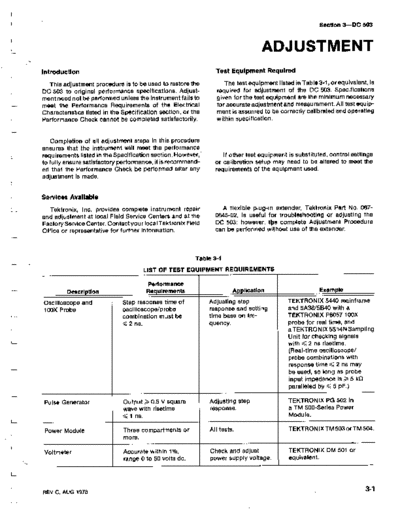
>> Download dc503 adjustment procedure documenatation <<
Text preview - extract from the document
                                                                                                        Section 3-DC 503


                                                                                  ADJUSTMENT
Introduction                                                    Test Equipment Required

   This adjustment procedure is to be used to restore the           The test equipment listed in Table 3-1, or equivalent, is
DC 503 to original performance specifications . Adjust-          required for adjustment of the DC 503. Specifications
ment need not be performed unless the instrument fails to        given for the test equipment are the minimum necessary
meet the Performance Requirements of the Electrical              for accurate adjustment and measurement . All test equip-
Characteristics listed in the Specification section, or the      ment is assumed to be correctly calibrated and operating
Performance Check cannot be completed satisfactorily .           within specification.


    Completion of all adjustment steps in this procedure
ensures that the instrument will meet the performance
requirements listed in the Specification section. However,         If other test equipment is substituted, control settings
to fully ensure satisfactory performance, it is recommend-      or calibration setup may need to be altered to meet the
ed that the Performance Check be performed after any            requirements of the equipment used .
adjustment is made .


Services Available

   Tektronix, Inc. provides complete instrument repair             A flexible plug-in extender, Tektronix Part No . 067-
and adjustment at local Field Service Centers and at the        0645-02, is useful for troubleshooting or adjusting the
Factory Service Center . Contactyour local Tektronix Field      DC 503; however, toe complete Adjustment Procedure
Office or representative for further information .              can be performed without use of the extender.


                                                         Table 3-1

                                     LIST OF TEST EQUIPMENT REQUIREMENTS

                                       Performance
         Description                   Requirements                    Application                      Example

Oscilloscope and              Step response time of           Adjusting step                TEKTRONIX 5440 mainframe
100X Probe                    oscilloscope/probe              response and setting          and 5A38/5B40 with a
                              combination must be             time base on fre-             TEKTRONIX P6057 100X
                                2 ns .                        quency .                      probe for real time, and
                                                                                            aTEKTRONIX 5S14N Sampling
                                                                                            Unit for checking signals
                                                                                            with < 2 ns risetime .
                                                                                            (Real-time oscilloscope/
                                                                                            probe combinations with
                                                                                            response time < 2 ns may
                                                                                            be used, so long as probe
                                                                                            input impedance is > 5 k()
                                                                                            paralleled by < 5 pF .)

Pulse Generator               Output > 0.5 V square           Adjusting step                TEKTRONIX PG 502 in
                              wave with risetime              response .                    a TM 500-Series Power
                              < 1 ns .                                                      Module .

Power Module                  Three compartments or           All tests.                    TEKTRONIX TM503orTM504 .
                              more .

Voltmeter                     Accurate within 1%,             Check and adjust              TEKTRONIX DM 501 or
                              range 0 to 50 volts dc .        power supply voltage.         equivalent .


REV C, AUG 1978
Adjustment-DC 503

                                                      Table 3-1 (cont)
                                        LIST OF TEST EQUIPMENT REQUIREMENTS

                                       Performance
         Description                  Requirements                       Application                 Example


10X Probe                     At least 1 Mtl input            Checking and setting         TEKTRONIX P6006, P6060,
                              resistance paralleled           time base frequency.         or equivalent.
                              by <, 30 pF .

50-f2 Feedthrough             Bnc connectors .                Step response                Tektronix 011-0049-01
Termination                                                   adjustment .                 or equivalent .

50-f2 Coaxial Cable           Bnc connectors .                Checking and setting         Tektronix 012-0057-01
(2 ea)                                                        time base frequency          or equivalent.
                                                              and step response .

Bnc 'T' Connector                                             Adjust step response .       Tektronix 103-0030-00
                                                                                           or equivalent.

Frequency Standard'           Output 1 V or more              Adjust time base .           WWV.
                              into 50 lZ load,
                              accurate within
                              1 part in 10 8, out-
                              put frequencies to
                              include 1 MHz.


'Traceable to NBS.


Preparation                                                     Initial Control Settings

   a. Remove the left side cover of the DC 503 to gain             Set the following controls during warm-up time :
access to the adjustments inside . Remove the cover by
                                                                                        DC 503
pulling the rear end outward from the side of the
instrument (the cover snaps into place) .                          FUNCTION                    .01 s
                                                                   CLOCK RATE                  10 6-1 s
                                                                   DISPLAY TIME                ccw
   b. Connect the DC 503 to the power module by means              CH A LEVEL                  midrange/in
of the flexible plug-in extender . If an extender is not           CH B LEVEL                  midrange/in
available, remove the cover fronrthe power module and              All front-panel
plug the DC 503 into the left compartment.                            pushbuttons              out

                                                                                        DM 501
   c. Be sure that the power switch on the power module
                                                                   Range/Function switch       20 DC Volts
is off. Set the power module for the line voltage to be
applied (see power module manual) .
                                                                1 . Adjust +15 V Supply
  d . Plug the power cord of the power module into the             a. Connect the DM 501 LO test lead to the DC 503
power source to be used and turn on the power module .          chassis ground (function of C502 and R506). Connect the
                                                                DM 501 HI test lead to the DC 503 +15 V test point (the
                                                                junction of R502, C502, and R504, see Fig. 3-1) .
  e . Connect all test equipment to a suitable line voltage
source . Turn on all test equipment and allow at least 20          b. Adjust R505 for a reading of +15.000 on the DM 501
minutes for the equipment to warm up and stabilize.             readout.


3-2                                                                                                     REV G, AUG 1978
                                                                                                                   Adjustment-DC 503


                          +5 V Test Point
                               R522


  +15 V Adjust
      R505

+15 V Test Point
     R502


       -22 V
     Test Point
        R542


                                                                                                                                  1411-08

                                                                    1 MHz
       Outline indicates area occupied by crystal oven            Test Point
       when option 1 is installed. Components inside             0272, Pin 5
       outline are removed when option is installed.

                                         Fig. 3-1 . Location of power supply test points and adjustment .


        c. Check that the +5 V and --22 V supplies are both                   g . Turn R42 slowly counterclockwise while watching
     within
◦ Jabse Service Manual Search 2026 ◦ Jabse Pravopis ◦ onTap.bg ◦ Other service manual resources online : Fixya ◦ eServiceinfo